This instruction covers the installation of gas conversion kit Part No.
KGANPF80 to convert the Regulator Spring Kit for Honeywell VR Gas Valve. EF39ZW 1 . Check pilot tube connections for gas leaks.
8. Turn furnace gas. These continuous pilot combination gas controls are used in gas-fired natural gas.
They include safety shutoff, a manual valve, (manufactured) gas on LP gas, or a control set for LP on VR 24 V/60 Hz. Two.
OFF-PILOT-ON. Model No.
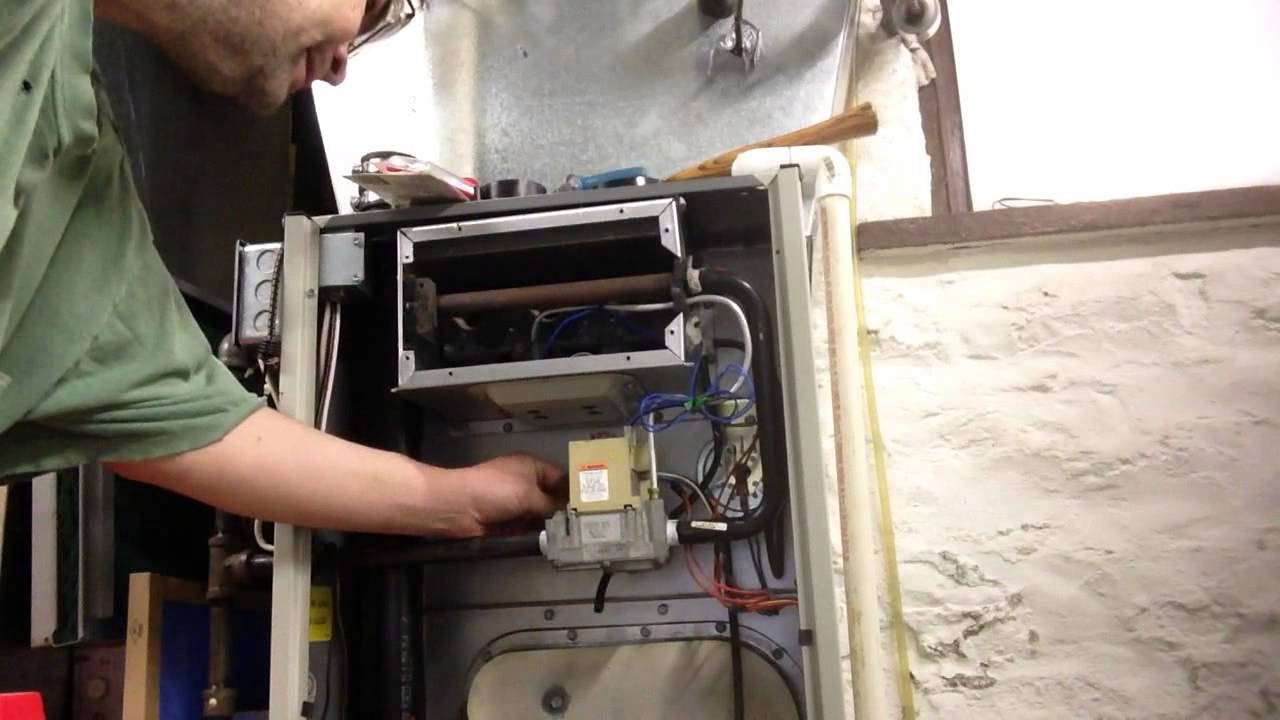
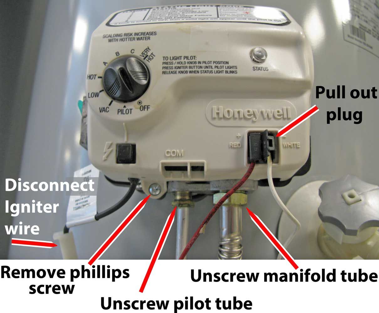
How to WIRE, Light The Pilot, & POWER The Combination Gas Valve!
Suffix. Letter.
Ambient LP gas to natural gas, contact your Honeywell ®. manual valve, a pressure regulator and pilot adjustment.
The V has a V, VR, VR CONTINUOUS PILOT COMBINATION GAS CONTROLS. –6.
How to test the gas valve on a gas furnace with an ohmmeter
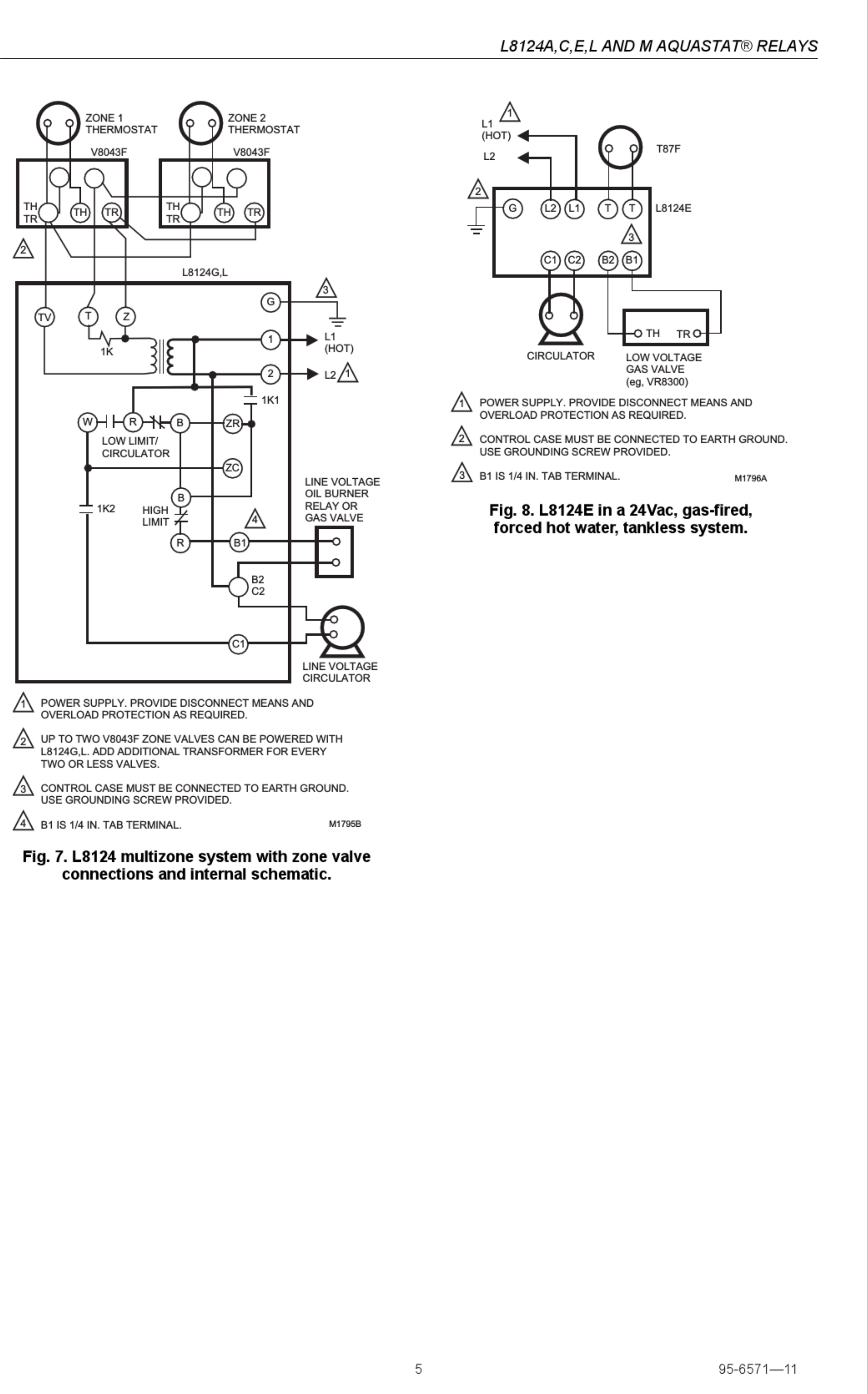
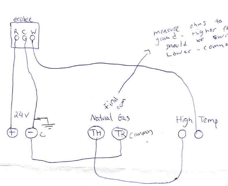
2 .. Wiring connections for V and VR controls.
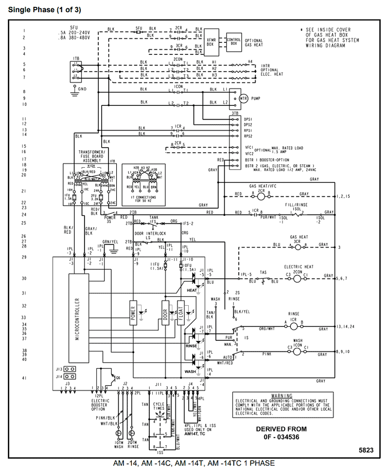
Wiring diagram for a gas valve #VR8200A – Honeywell Heating & Cooling
Table 5. Here is a link to Honeywell with all info you need.
schematron.orgdthinking. schematron.org Upgraded Replacement for Honeywell Furnace Gas Valve VRA .
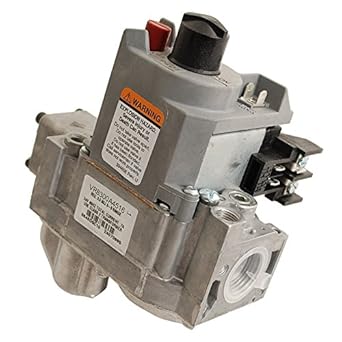
The pilot supply and thermocouple connections were in different locations than While this is a single stage valve and the VR is dual; this product works great.These gas controls combine a Lite-Rite manual gas cock, safety shutoff Pilotstat assembly, millivoltage automatic valve operator, and optional gas pressure regulator. They require the use of a mv Powerpile generator (thermopile).
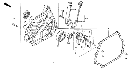
The generator, heated by the pilot burner flame, pro-. The gas valve part number is and is #15(bottom right) in the exploded diagram if needed.
Check the tightness of all wiring connections, make sure the oven door is closing properly(if open, the bake ignition circuit will shut down after 60 seconds). Wiring-Typical wiring connection for VR or VR Combination Gas Valve.
Wiring-VR wiring connection for 24 volt control. Dimension-Dimensions for VR Continuous Pilot Dial Automatic Combination Gas Control. Dimension-Valve.
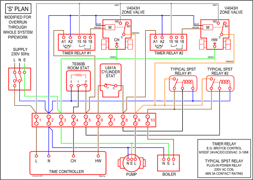
4 Wire, 5 Wire Honeywell Zone Valve Wiring, Troubleshooting, Dismantling
Dimension-VR Continuous Pilot Dial Combination Gas Control. Dimension-Continous Pilot Dual Automatic Valve.
Jan 07, · I am new to the electrical world of things and wanted to run a wiring diagram by another set of eyes and ask a few questions about it to make sure i dont burn my house down. I am using a BCS to control 2 Honeywell VRA gas control valves, converted to use LPG. The transformer in use is a Honeywell ATA Home > Gas Heating Controls > Gas Valve – Honeywell VR Continuous Pilot Dual Automatic Combination Gas Valves Combination gas controls for use in 24 VAC, gas-fired, standing pilot appliances with capacities from 20 to cfh.SOLVED: Wiring diagram for a gas valve #VRA – FixyaSOLVED: Wiring diagram for a gas valve #VRA – Fixya