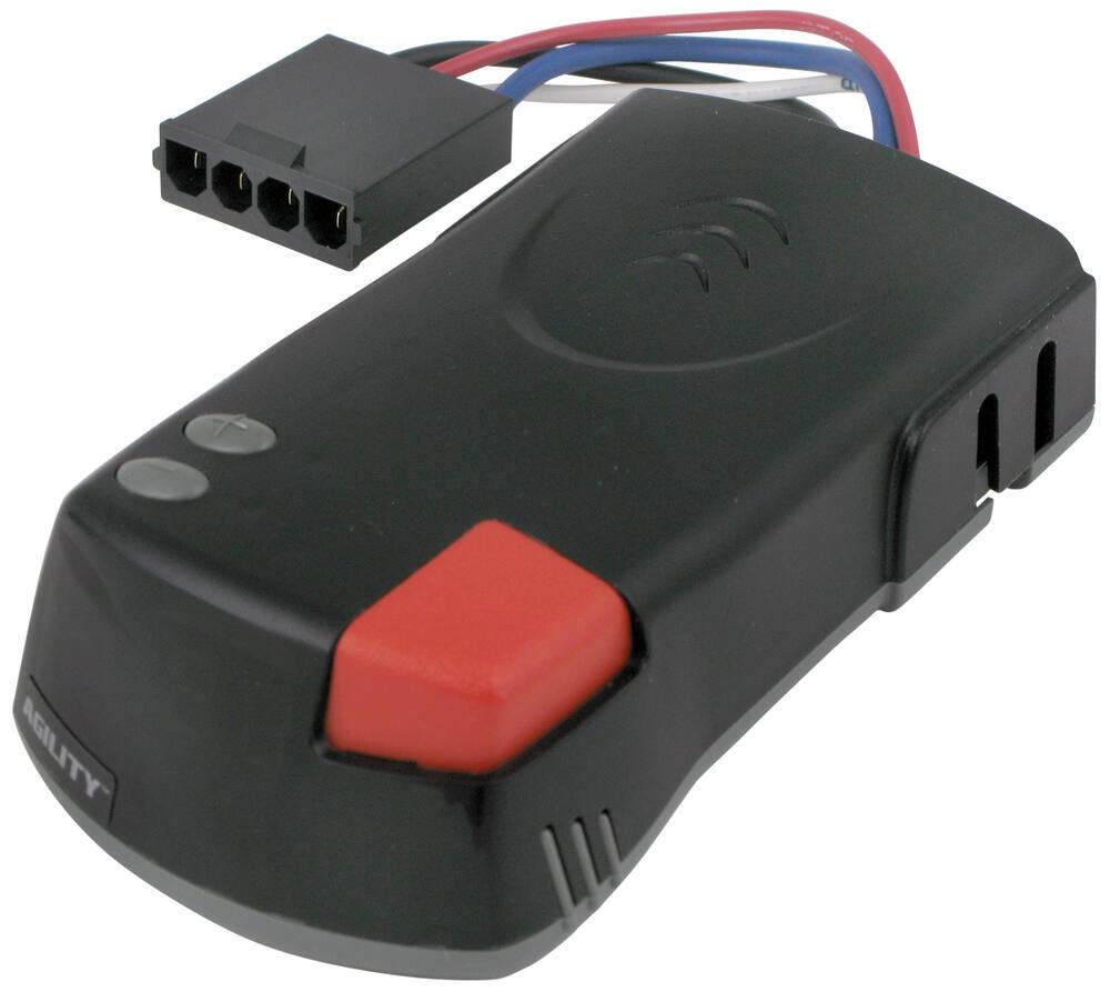
Impulse™ Brake Control. stars 1 Review?Share.

Installation Instructions. Time-based braking; Mounts at any angle; Percentage of braking power shown.
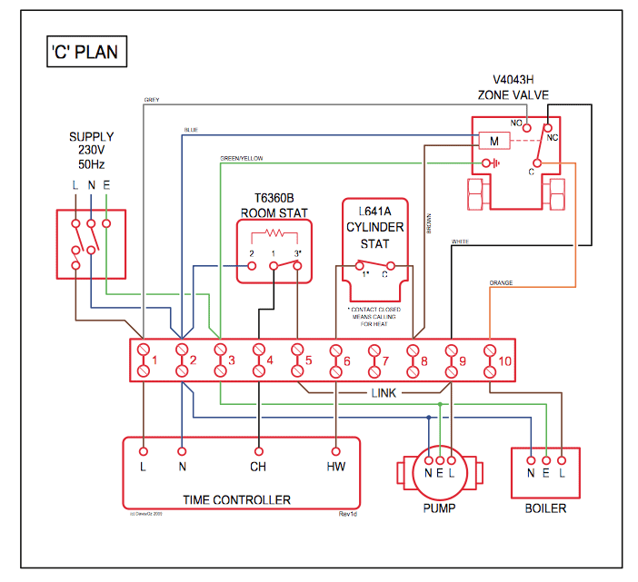
You can use the Hopkins Plug-in Simple Brake Wiring Adapter, # HM, but you will need to clip off the vehicle side connector (larger brown square plug). Wiring Harness to Install Hopkins Impulse Brake Controller in a Toyota I have a Toyota 4Runner and an Hopkins Impulse Break Controller, I just need to Wiring Diagram to Install Hopkins Proportional Brake Controller in a From to , GM trucks did not use plug-in style brake controller wiring. Instead, they had 4 (sometimes 5) blunt cut wires bundled up under the drivers.
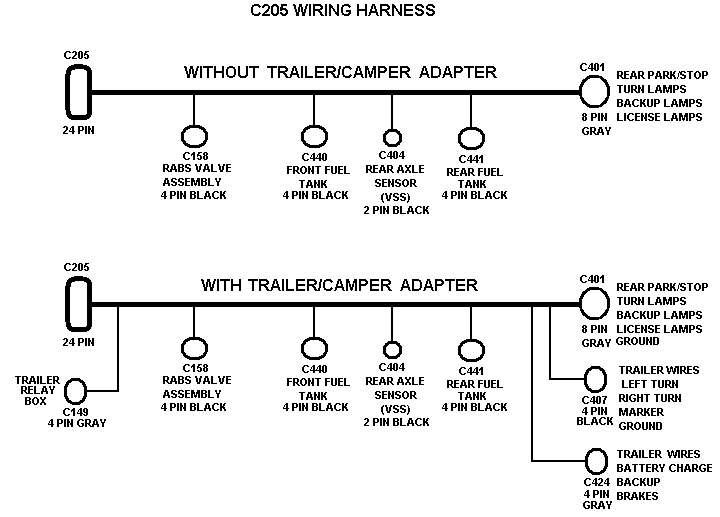
Wiring Diagram to Install Hopkins Proportional Brake Controller in a Chevy What does the SC Error Code Mean on a Hopkins Impulse Brake Controller.had my controller for 7 years towing horses on a regular bases thought i had a problem with it turned out to be a fuse not the controller recommend this highly. You almost certainly already know that hopkins brake controller wiring diagram is one of the top issues on the net now.
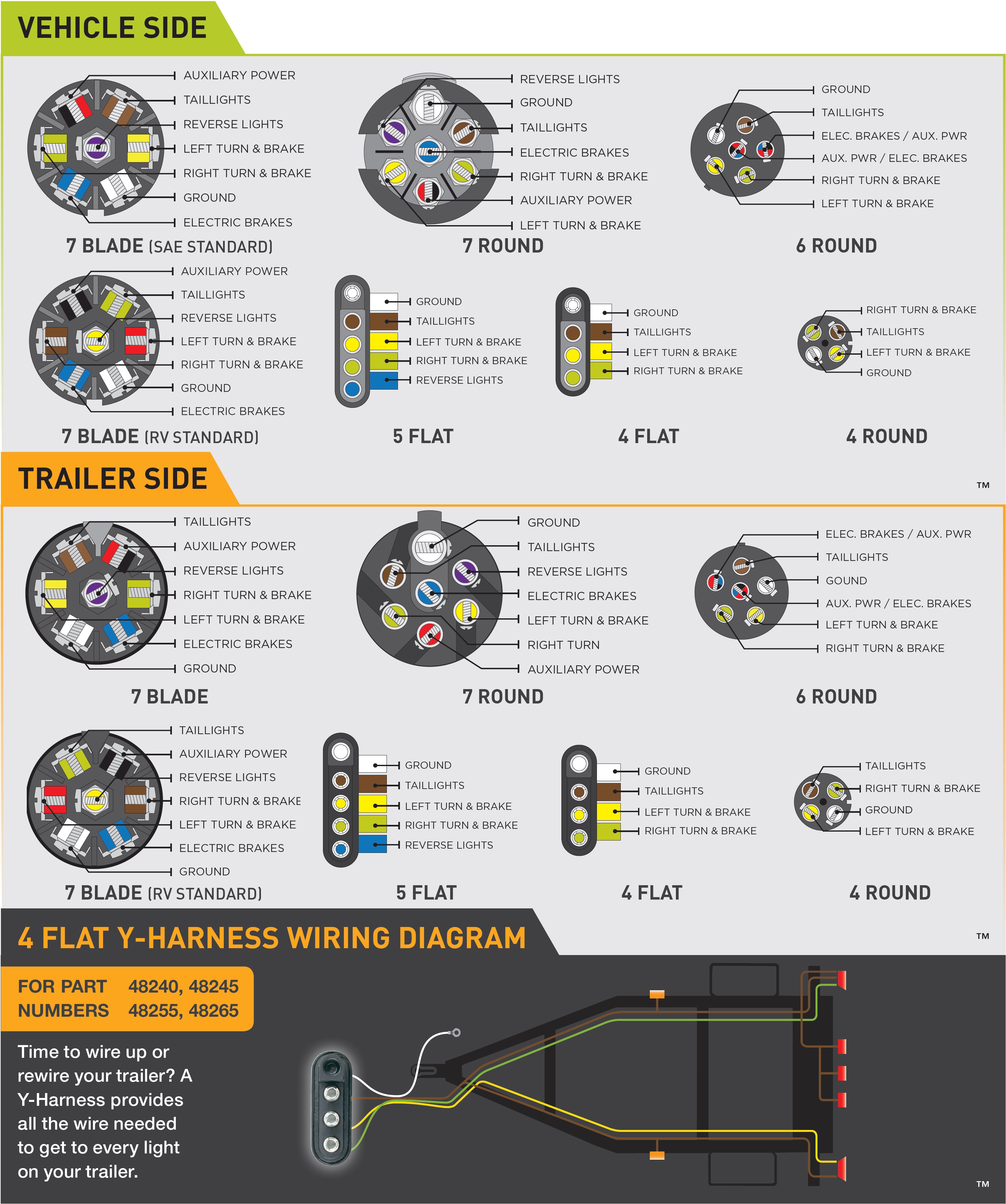
Depending on the files we got from google adwords, hopkins brake controller wiring diagram has very much search in google search engine. Plug wiring to controller.

Impulse™ brake control products to be free from defects in material and workmanship, under normal use and service, for the original buyer’s The correct wire is located in position “F”. ® BRAKE CONTROL E HOPKINS. UNIVERSAL INSTALLATION. Everything from trailer wiring harnesses, connectors, and adapters to brake controllers, trailer break-away kits, and rear view camera systems, you can count on Hopkins to make towing safe and enjoyable.
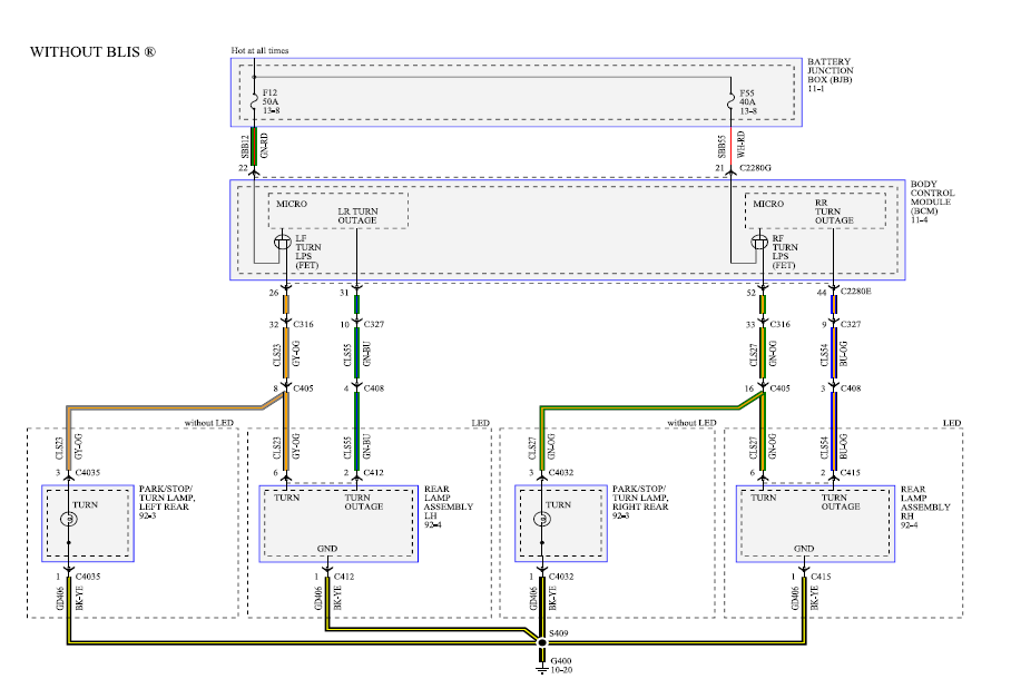
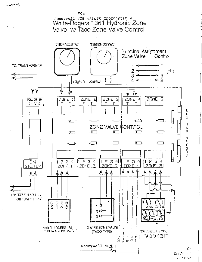
Hopkins Impulse Trailer Brake Controller Wiring Diagram – Hopkins brake controller wiring diagram – A schematic shows the plan and function on an electrical circuit, but isn’t worried with the physical layout from the wires. Wiring diagrams display how a wires are related and wherein they have to based totally inside the actual device, plus the.Impulse™ Brake ControlImpulse Brake Controller Wiring Diagram | Trusted Manual & Wiring Resources
