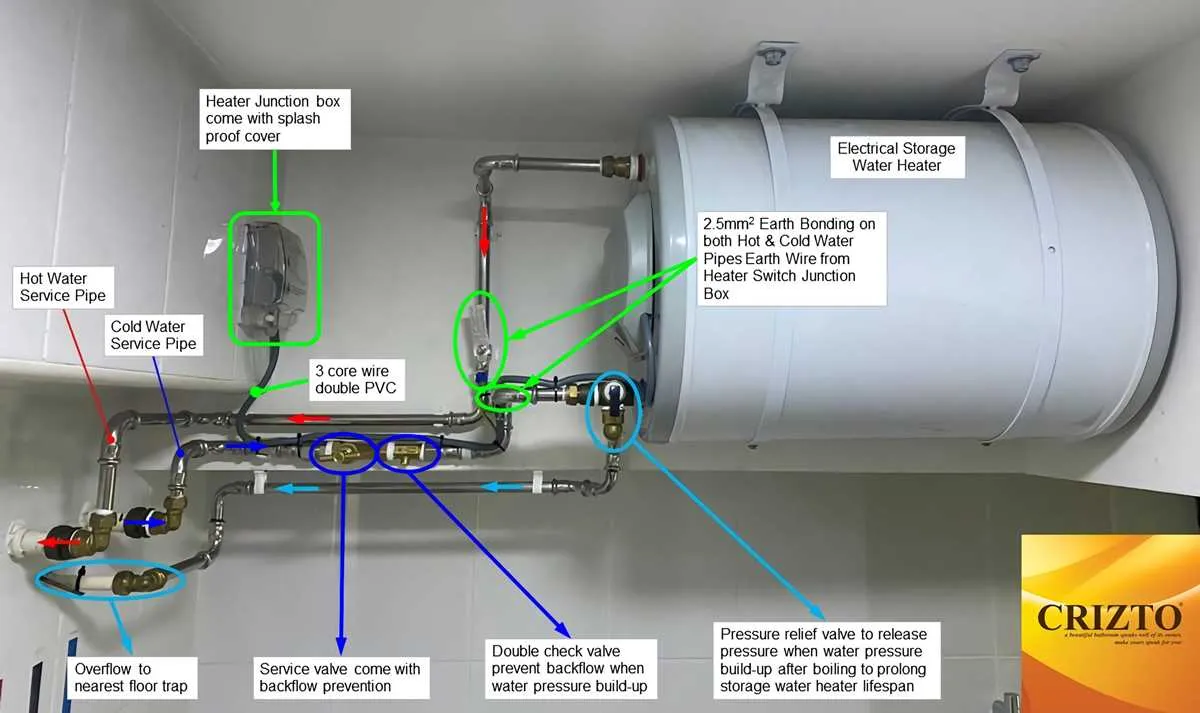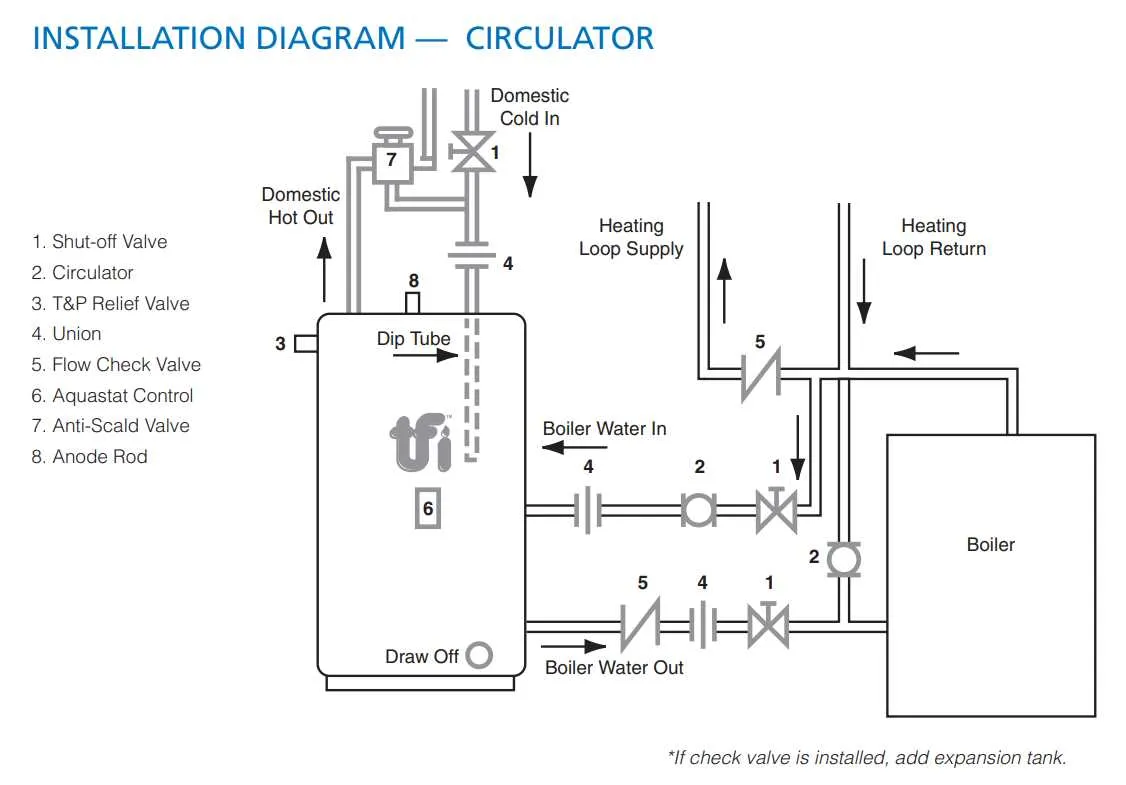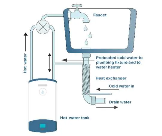
To ensure efficient operation and prevent common issues, it’s crucial to correctly connect the primary components that manage temperature control in your home’s pipeline. A clear understanding of how each element interacts with others is key for both installation and troubleshooting. Accurate installation guarantees optimal performance and safety.
First step: Identify where the input and output pipes should be placed for seamless fluid flow. The cold supply must be routed to the intake side, while the heated fluid exits from the top section. This setup ensures that the device can cycle through and maintain the correct internal pressure and temperature.
Next, focus on connections: Valves, pressure relief systems, and the venting process are critical for safety and function. Without proper venting, excess heat could lead to failure or damage. Pay particular attention to ensuring each connection is tightly sealed to prevent leakage, which could compromise efficiency.
Lastly, always consider the system’s power source and energy efficiency options. Using a reliable thermostat that regulates internal temperature will minimize excess energy consumption while extending the lifespan of the unit. Regular maintenance of these connections will also avoid costly repairs in the long run.
System Layout for Domestic Heat Storage Unit

Ensure a well-planned configuration for optimal performance of your heat storage unit. Follow these key installation guidelines:
- Connect the cold supply line directly to the intake valve, ensuring a tight seal to prevent leaks.
- Position the output pipe from the storage unit towards the nearest fixture to minimize energy loss.
- Install a pressure relief valve near the top of the tank to regulate excess pressure, preventing potential damage.
- Ensure that the venting system allows proper air circulation to avoid overheating of the system.
- Install a drain valve at the bottom for maintenance and sediment removal.
- Use high-quality connectors and flexible hoses to avoid wear and tear over time.
- Consider placing an insulating jacket around the tank to maintain temperature and improve efficiency.
Always verify local codes and regulations to ensure compliance during installation.
Understanding the Basic System Setup

Start by ensuring that the inlet and outlet pipes are correctly connected to the tank. The cold supply should be routed into the lower portion of the unit, while the hot outlet should exit from the top. This setup allows for efficient temperature control and flow management.
The temperature control valve should be adjusted to the desired heat level, typically set between 120°F and 140°F for optimal performance. It’s crucial that this setting is monitored regularly to prevent overheating, which can cause damage to the system and increase energy consumption.
Ensure the pressure relief valve is installed and functioning properly. This valve is essential for safety, releasing excess pressure that could otherwise cause a malfunction or burst. It should be tested annually to guarantee it works as intended.
If a circulating pump is used, make sure it is correctly connected to the system. The pump helps maintain consistent temperature levels throughout the system and prevents cold spots. If not installed properly, it can lead to uneven heating and inefficiencies.
Lastly, consider insulating all exposed pipes to reduce heat loss, which will improve energy efficiency and prevent freezing in colder climates. Insulation material should be durable and resistant to moisture buildup to avoid long-term damage.
Common Issues in Water Heating Systems and How to Fix Them
Start by checking for inconsistent temperatures. If the heat output fluctuates, inspect the thermostat setting and the element connections. A malfunctioning thermostat may require replacement, or you might need to recalibrate it to ensure stable performance.
If the unit fails to produce sufficient heat, sediment buildup in the tank can be the culprit. Drain the system and flush it to remove accumulated minerals. Regular maintenance can prevent future blockages and efficiency loss.
In case of leakage around the connections, verify the tightness of all fittings and seals. Tighten them if necessary. Leaks from the bottom may indicate a tank rupture, which usually requires complete replacement of the unit.
If you hear unusual noises such as popping or banging, sediment might be causing it. Flushing the tank resolves this problem. Additionally, check the anode rod condition. If it’s deteriorated, replace it to prevent further corrosion of the interior.
If the device is not turning on, inspect the power source. Check if the breaker has tripped or the fuse has blown. For electric units, test the heating element for continuity using a multimeter. If defective, the element needs replacement.
Inconsistent pressure from the output can be a result of clogged pipes or a faulty pressure relief valve. Inspect both, clean out any blockages, and replace the valve if necessary. This will restore proper flow and ensure safety.
How to Properly Install a Heating Unit with a Detailed System Setup
Before starting the installation, ensure the power supply is switched off and the location is prepared for the device. Position the unit close to the main supply pipe and ensure there is adequate ventilation.
1. Connect the Cold Inlet Pipe
Start by attaching the cold supply pipe to the inlet valve of the unit. Use a pipe wrench to securely fasten the connection. Make sure the pipe is properly aligned to avoid any stress on the fittings, which could cause leaks.
2. Attach the Outlet Pipe
Next, connect the outlet pipe to the designated valve on the device. This pipe will carry heated fluid to the points of use. Ensure the pipe is correctly routed with no bends or kinks to maintain proper flow and pressure.
3. Secure the Venting System
If the system requires venting, install the exhaust pipe, ensuring it runs vertically or at an angle for proper ventilation. Secure all joints using high-temperature resistant tape or sealant to prevent any gas leakage. Double-check the alignment with local building codes.
4. Electrical Wiring
For electrically powered units, connect the necessary electrical wires to the unit’s terminals. Ensure the circuit is properly grounded, and use a dedicated circuit breaker to protect against overloads. Always check the unit’s voltage requirements to match the wiring specifications.
5. Check and Test
Before finishing the installation, check for leaks by turning on the supply and inspecting all connections. Test the unit’s operation by activating it according to the manufacturer’s instructions, ensuring it functions as expected.
Note: Ensure that the device’s drain valve is also installed, in case any maintenance is needed. Regular checks will help maintain long-term efficiency and avoid unexpected failures.