Check out Mustang Hurst Line Lock () Installation Instructions at CJ Pony Parts. Required tools and images are included in this guide.

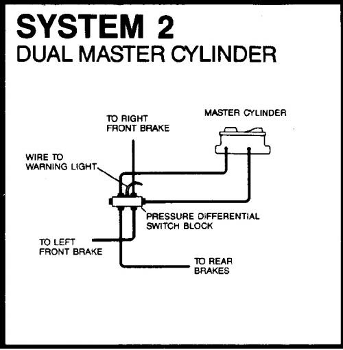
wrench is recommended on all line fittings while in- stalling the brake vice, a rebuild kit is available from your local HURST performance trol on vehicles equipped with anti-lock or split diagonal of improper installation that could render the vehi- cle unsafe and locate the comparable system on the diagrams to install. switch must be installed if the brake lock defeats the purpose/function of the stock a line fitting wrench is always recommended on all line fittings while install. Shop This Hurst Line Lock – Roll Control Kit: schematron.org Subscribe for New Mustang Videos Daily.
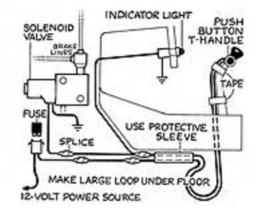
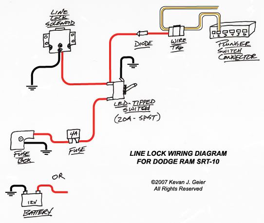
This switch kit can be used with any system (Line Lock, Nitrous, Transbrake) to fuse holder with a 4-amp fuse is provided (See wiring diagrams for wiring.Mar 31, · – Ground line lock unit at closest chaisis spot. – Ran a single wire inside the car through gromet by brake cylinder.
This is for powering the line lock. – Inside the car I used the cig lighter for power.
Used a simple splice/tap connector to tap the wire with out having to cut it. – The switch goes in the power line with a fuse. fuse holder with a 4-amp fuse is provided (See wiring diagrams for wiring details) and should be incorporated into the wiring circuit.
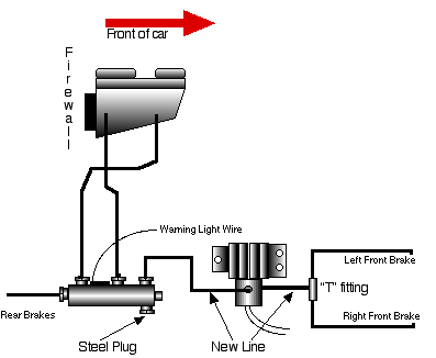
The fuse can protect the . front brake line from screwing into the Hurst brake line. Unscrewing Master Cylinder rear brake line might be required to move flex line.
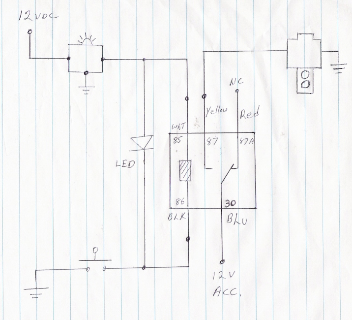
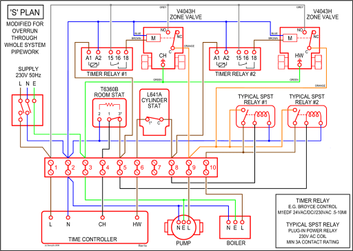
(See wiring diagrams for wiring details on page 10) and Hurst Roll Control brake line into the adapter, finger may be required for proper alignment). Once line is. Below is a picture of my Hurst Line Lock and a diagram of how I wired it. I disliked the large red bulb supplied with the Hurst kit so I wired it to light the factory BRAKE idiot light in the dash instrument cluster.
Wiring: All wiring connections should be soldered and covered with shrink sleeving. 1. Disconnect battery.
2. Wire per diagram on next page. 3.
Reconnect battery and test for correct operation. Operation: TO ACTIVATE: Depress brake pedal and hold, depress control switch and hold, release brake pedal. Brakes are now locked.Line lock wiring [Archive] – NJFBOA – Home of New Jersey’s Camaros and FirebirdsHurst Line Lock Diagram – schematron.org
