
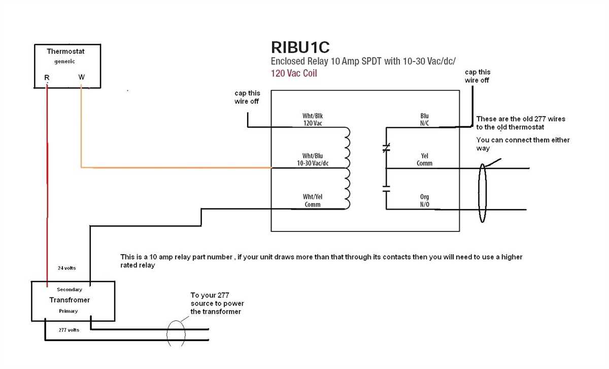
When it comes to the installation and maintenance of HVAC systems, it is important to have a good understanding of the wiring diagram, especially for the condenser. The condenser is a crucial component in the overall functioning of the HVAC system, as it helps in cooling and dehumidifying the air before it is circulated back into the building.
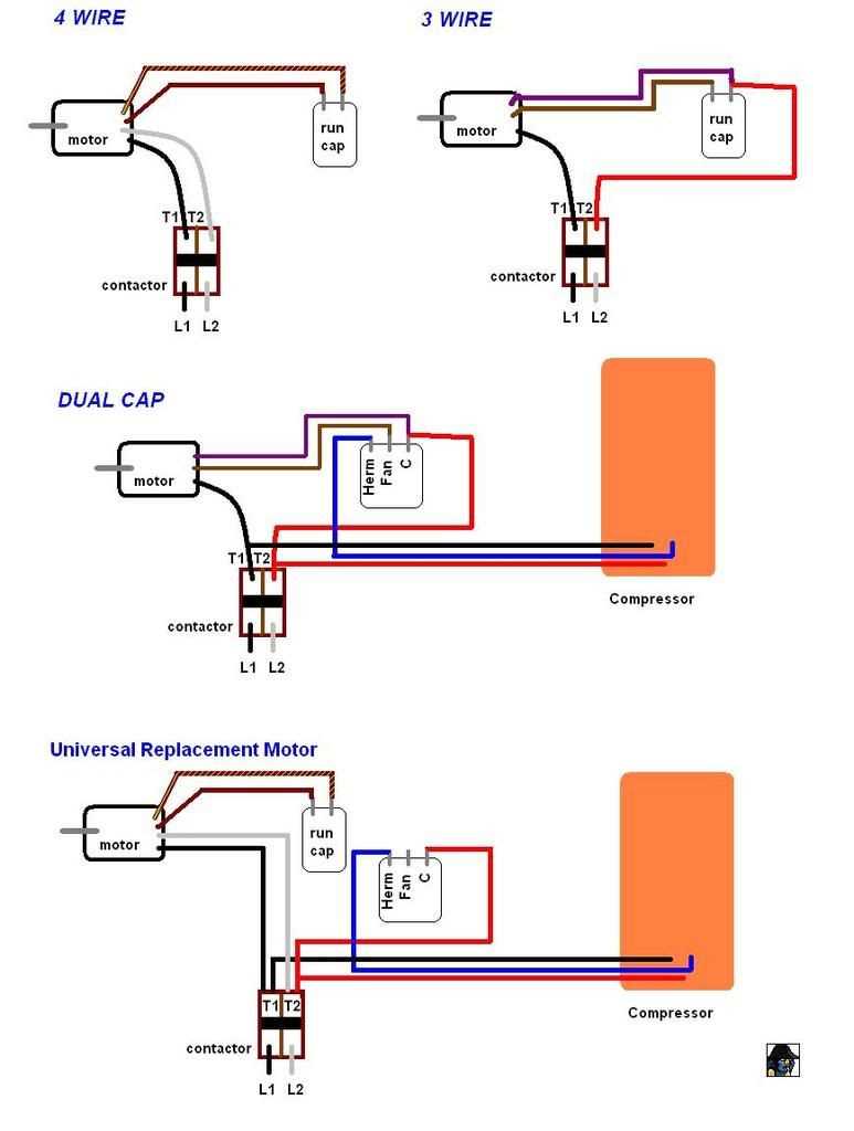
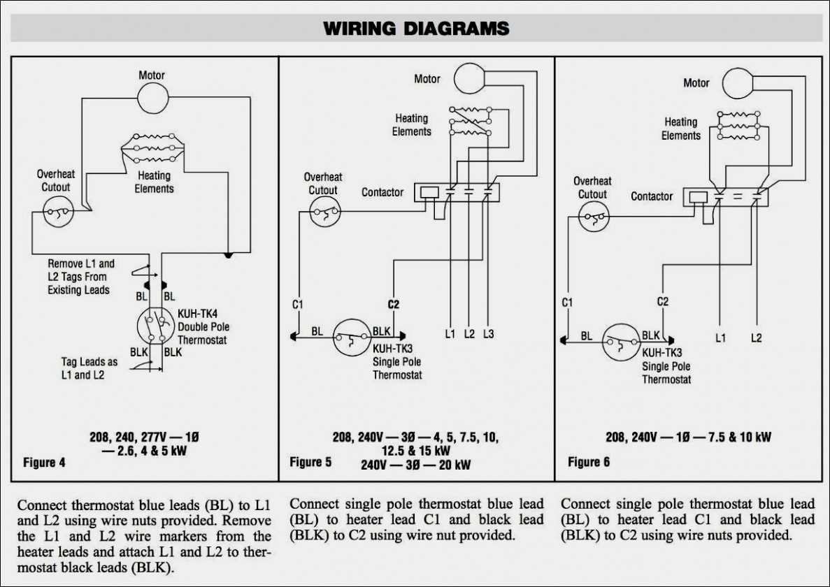
The wiring diagram for the HVAC condenser provides a visual representation of how the different components are connected together. It shows the electrical connections between the condenser motor, compressor, and the other components such as the contactor, capacitor, and the fan motor. Understanding this diagram is essential for troubleshooting issues and ensuring proper installation of the condenser.
One of the key aspects of the HVAC condenser wiring diagram is the use of color-coded wires. This is done to ensure that the correct wires are connected together, thus minimizing any errors or damage to the system. Common colors used in these diagrams include yellow for the compressor motor, red for the high-voltage power supply, and green for the fan motor.
By studying and understanding the HVAC condenser wiring diagram, HVAC technicians and installers can effectively diagnose and resolve any issues that may arise. It also helps in ensuring that the condenser is wired correctly, thereby optimizing the performance and efficiency of the HVAC system.
Hvac Condenser Wiring Diagram
In an HVAC (heating, ventilation, and air conditioning) system, the condenser is an essential component that helps cool the refrigerant before it returns to the evaporator. To properly wire the condenser, a wiring diagram is needed to ensure correct connections and operation. The HVAC condenser wiring diagram provides a visual representation of the electrical components and their connections within the condenser unit.
Basic Wiring Components:
- Power Supply: The condenser requires a power supply to operate, typically from a circuit breaker or fuse box.
- Contactor: The contactor is an electromagnetic switch that controls the flow of electricity to the condenser’s compressor.
- Motor: The motor is responsible for driving the condenser fan, which helps dissipate heat from the system.
- Capacitor: The capacitor stores electrical energy and provides a boost to start the condenser’s motor.
- Thermostat: The thermostat signals the condenser to turn on or off depending on the desired temperature settings.
- Low Voltage Wiring: Low voltage wiring connects the thermostat to the condenser, allowing for communication and control of the system.
Wiring Diagram:
| Wire Color | Function |
| Red | Power Supply |
| Yellow | Contact to Compressor |
| Blue | Contact to Fan Motor |
| Brown | Common (C) |
| Green | Ground |
Following the wiring diagram, the condenser’s power supply is connected to the red wire, while the yellow wire connects to the compressor. The blue wire is used to connect the condenser’s contact to the fan motor, and the brown wire is used as the common (C) connection. Finally, the green wire is connected to ground.
Proper wiring of the HVAC condenser is crucial for the unit to operate efficiently and effectively. It is important to follow the manufacturer’s instructions and consult the wiring diagram to ensure correct connections are made. If in doubt, it is advisable to seek professional assistance or consult a certified HVAC technician.
What is an HVAC Condenser?
An HVAC condenser is an important component of a heating, ventilation, and air conditioning (HVAC) system. It is responsible for releasing heat that has been absorbed by the refrigerant in the system.
The condenser is typically located outside of a building and works in conjunction with the compressor and evaporator coils to cool and dehumidify the air. It receives high-pressure, high-temperature refrigerant vapor from the compressor, and its main function is to convert the vapor back into a liquid state by removing heat from it.
The condenser consists of several key components, including the condenser coil, condenser fan, and condenser unit. The condenser coil is a network of tubes that are designed to efficiently transfer heat from the refrigerant to the surrounding air. The condenser fan helps to draw air across the condenser coil, assisting in the heat transfer process. The condenser unit contains the compressor, condenser coil, and fan, and is typically housed in a metal cabinet to protect it from weather elements.
In addition to its cooling function, the condenser also plays a role in the refrigeration cycle of the HVAC system. As the refrigerant is condensed into a liquid state, it releases heat energy into the surrounding air, which is then blown away by the condenser fan. This allows the refrigerant to absorb heat from the indoor air when it is circulated through the evaporator coil, cooling the air that is then distributed throughout the building.
Overall, the HVAC condenser is an essential component in maintaining the comfort and efficiency of a building’s cooling system. It plays a crucial role in the heat transfer process and helps to ensure that the air conditioning system operates effectively.
Importance of Proper Wiring in HVAC Condenser
Wiring is a crucial aspect of any HVAC system, especially in the condenser unit. The condenser is responsible for releasing heat from the refrigerant, and a properly wired system ensures its efficient operation. Without proper wiring, the condenser may not function correctly, leading to decreased cooling performance and potential damage to the unit.
One of the key reasons why proper wiring is important in an HVAC condenser is for safety. Incorrect or faulty wiring can pose a risk of electrical shock or fire hazard. A properly wired condenser ensures that the electrical connections are secure and effectively grounded, reducing the likelihood of electrical accidents.
Additionally, proper wiring in the condenser ensures the correct flow of electricity to various components of the unit, such as the fan motor, compressor, and capacitor. Each of these components plays a crucial role in the cooling process, and any wiring issues can lead to improper functioning or even failure of these components. With proper wiring, the electrical current is evenly distributed, allowing each component to work efficiently and maintain optimal performance.
Moreover, proper wiring in the condenser simplifies troubleshooting and maintenance. When the wiring is organized and properly labeled, it becomes easier for HVAC technicians to identify and fix any issues that may arise. They can quickly locate and replace faulty wires or connections, ensuring minimal downtime and avoiding costly repairs.
In conclusion, proper wiring in an HVAC condenser is essential for safety, efficient operation, and ease of maintenance. It ensures the safe and reliable functioning of the unit, allowing for effective cooling performance and avoiding potential hazards. Investing in professional installation and regular inspections of the wiring can help maximize the lifespan and performance of the HVAC condenser.
Components of an HVAC Condenser Wiring Diagram
A wiring diagram is a visual representation of the electrical connections and components within an HVAC condenser unit. It provides a detailed overview of how the various parts are connected and helps technicians troubleshoot and repair any issues that may arise.
1. Compressor: The compressor is the heart of the HVAC system and is responsible for pumping refrigerant throughout the system. It is typically represented as a circle with the letter “C” inside it on the wiring diagram.
2. Fan Motor: The fan motor is responsible for moving air across the condenser coils to dissipate heat. It is represented by the letter “F” on the wiring diagram. There may be multiple fan motors depending on the specific system.
3. Capacitor: The capacitor is an electrical component that stores and releases electrical energy to start and run the motors. It is often represented by the letter “C” or a squiggly line on the wiring diagram. There may be separate capacitors for the compressor and fan motor.
4. Contactor: The contactor is an electromagnetic switch that controls the flow of electricity to the compressor and fan motor. It is typically represented as a rectangle with the letter “M” inside it on the wiring diagram.
5. Thermostat: The thermostat is the interface between the user and the HVAC system. It sends signals to the condenser unit to turn on or off based on the temperature settings. The wiring diagram may include the thermostat connections and wiring details.
6. Power Supply: The power supply provides the electrical energy needed to operate the condenser unit. It is usually represented by the letter “L” for line voltage and “N” for neutral on the wiring diagram.
7. Safety Switches: HVAC condenser units are equipped with safety switches to protect against electrical faults and malfunctions. These switches may include high-pressure switches, low-pressure switches, and disconnect switches. The wiring diagram may indicate the location and connections of these safety switches.
The wiring diagram provides technicians with a clear understanding of the electrical connections and components within an HVAC condenser unit. It allows them to diagnose and repair any electrical issues efficiently, ensuring the proper functioning of the system.
Common Wiring Diagrams for HVAC Condensers
In this article, we have explored the common wiring diagrams for HVAC condensers. These diagrams provide a visual representation of how the various components of an HVAC condenser are connected. They are essential for properly installing and troubleshooting the condenser unit.
Condenser wiring diagrams typically include the following components:
- Power supply connection
- Compressor
- Condenser fan motor
- Capacitor
- Thermostat
- Control board
By understanding and following these wiring diagrams, HVAC technicians can ensure that the condenser unit operates efficiently and safely. They can easily identify and diagnose any wiring issues that may be affecting the performance of the condenser.
It is important to note that these wiring diagrams may vary depending on the specific make and model of the HVAC condenser. HVAC technicians should always refer to the manufacturer’s documentation and follow the wiring diagrams provided for the specific unit they are working on.
In conclusion, having a good understanding of the common wiring diagrams for HVAC condensers is crucial for HVAC technicians. It allows them to properly install, maintain, and troubleshoot condenser units, ensuring optimal performance and longevity.
Q&A:
What is a wiring diagram for an HVAC condenser?
A wiring diagram for an HVAC condenser is a visual representation of the electrical connections and components involved in the condenser unit of an HVAC system.
What does a common wiring diagram for an HVAC condenser include?
A common wiring diagram for an HVAC condenser includes the power supply connections, the compressor and fan motor connections, the fan and capacitor wiring, and any other electrical components in the condenser unit.
Why is a wiring diagram important for an HVAC condenser?
A wiring diagram is important for an HVAC condenser because it provides a roadmap for technicians to properly install and troubleshoot the electrical connections in the condenser unit. It ensures that the system operates safely and efficiently.
Can I find a wiring diagram for my specific HVAC condenser model?
Yes, you can usually find a wiring diagram for your specific HVAC condenser model in the installation manual or technical documentation provided by the manufacturer. You can also consult with a professional HVAC technician for assistance.
Are there any online resources available for finding common wiring diagrams for HVAC condensers?
Yes, there are several online resources available where you can find common wiring diagrams for HVAC condensers. Some manufacturers provide wiring diagrams on their websites, and there are also websites and forums dedicated to HVAC technology that may have wiring diagrams available for reference.
What is a wiring diagram for an HVAC condenser?
A wiring diagram for an HVAC condenser is a visual representation of the electrical connections that need to be made in order to properly install and operate the condenser unit. It shows the various components and their electrical connections, including the power supply, control wires, and any additional devices such as thermostats or pressure switches.
What are some common wiring diagrams for HVAC condensers?
There are several common wiring diagrams for HVAC condensers, depending on the specific requirements of the system. Some common types include single-phase wiring diagrams, three-phase wiring diagrams, and low-voltage control circuit diagrams. The specific diagram will vary based on factors such as the type of condenser unit, the power supply available, and the control system being used.