Here is a basic wiring diagrams, Understanding wiring diagrams for HVAC/R.
Wiring Diagram with Mark Tyrrell E4
wink hvac. Loading Unsubscribe from wink hvac?
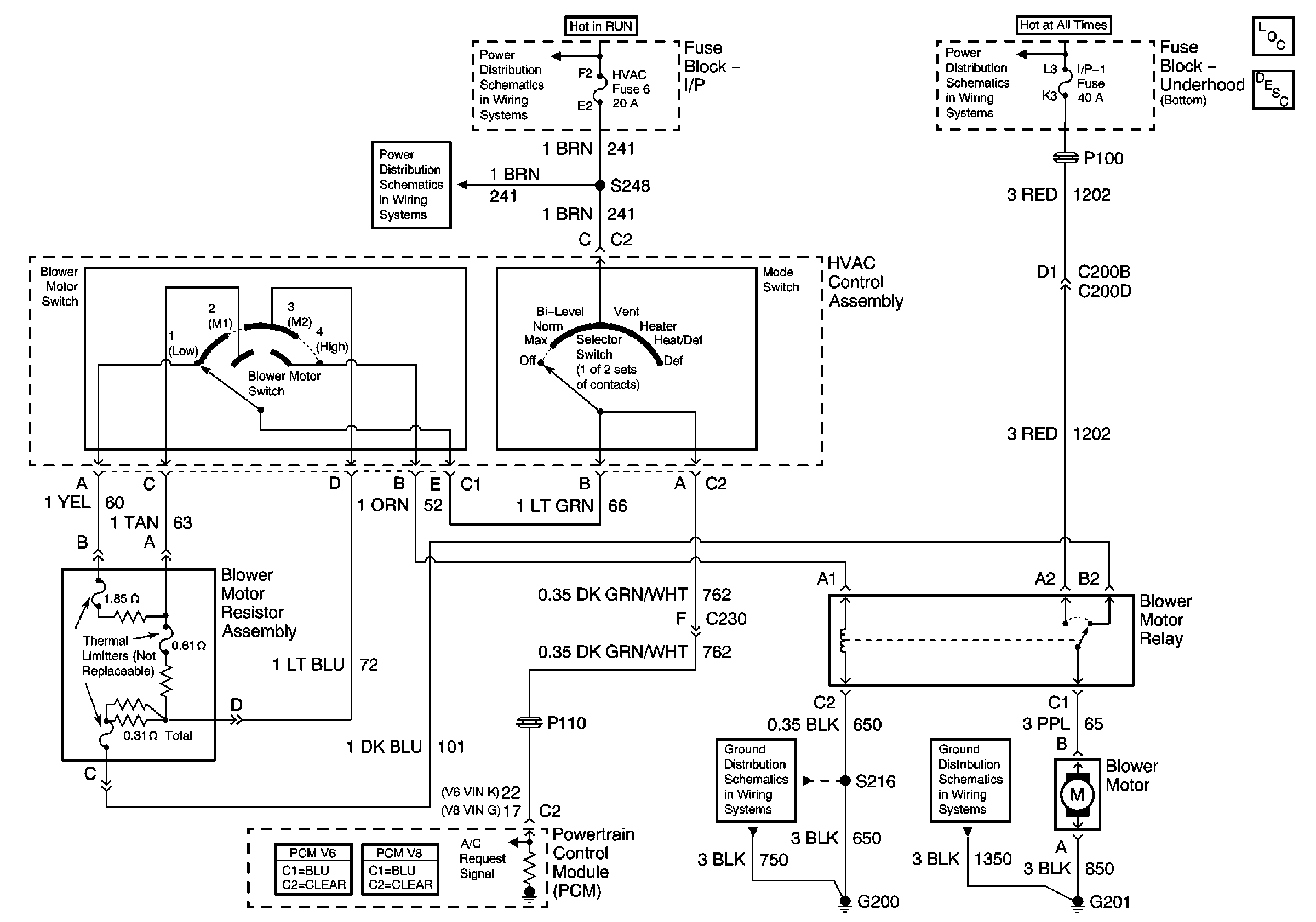
Cancel. Thermostat Wiring Diagrams – Heat pumps are wired for HVAC control far differently than air conditioning systems so make sure you know the difference and. At first glance, HVAC wiring diagrams look intimidating, just as intimidating as a roadmap did the first time you glanced at one of those.
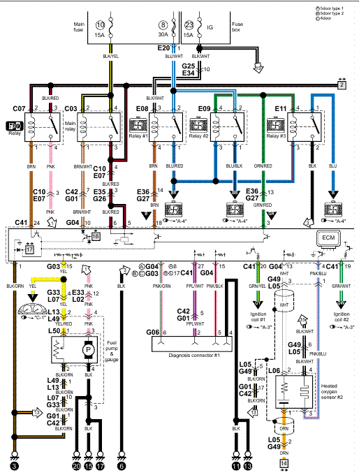
Roadmaps and wiring. Wiring for field power supply must be rated at 60 C minimum.
HVAC Wiring Diagrams 2
Use .. 6 — Wiring Diagram; 50BYN Unit With Temp Thermostat . 24V-DO NOT USE HVAC.
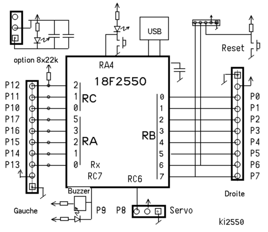
If you are unsure about the control voltage of your system consult an HVAC professional Air Conditioner Control – Thermostat Wiring Diagram – HVAC Systems.May 24, · I demonstrate how easy it is to use the wiring diagram to figure out where the wires go. Attention: Do not try any of what you see in this video at home.
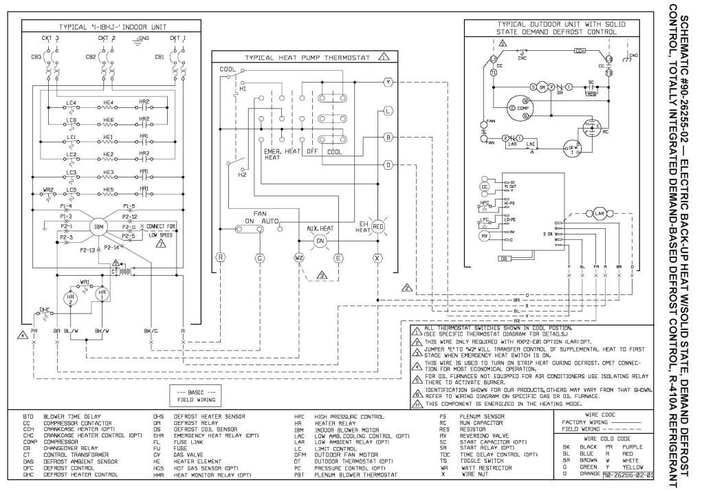
How to Wire an Air Conditioner for Control – 5 Wires. How to Wire an Air Conditioner for Control – 5 Wires – The diagram below includes the typical control wiring for a conventional central air conditioning schematron.org includes a thermostat, a condenser, and an air handler with a heat source. I have a Fb4an hat pump and Im looking for a wiring diagram.
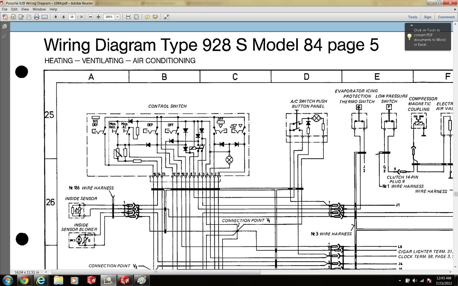
I have a Fb4an hat pump and I’m looking for a wiring diagram. I had a technician come out and service the unit and he messed up the wiring and the heading coils are on perpetually. Fig.
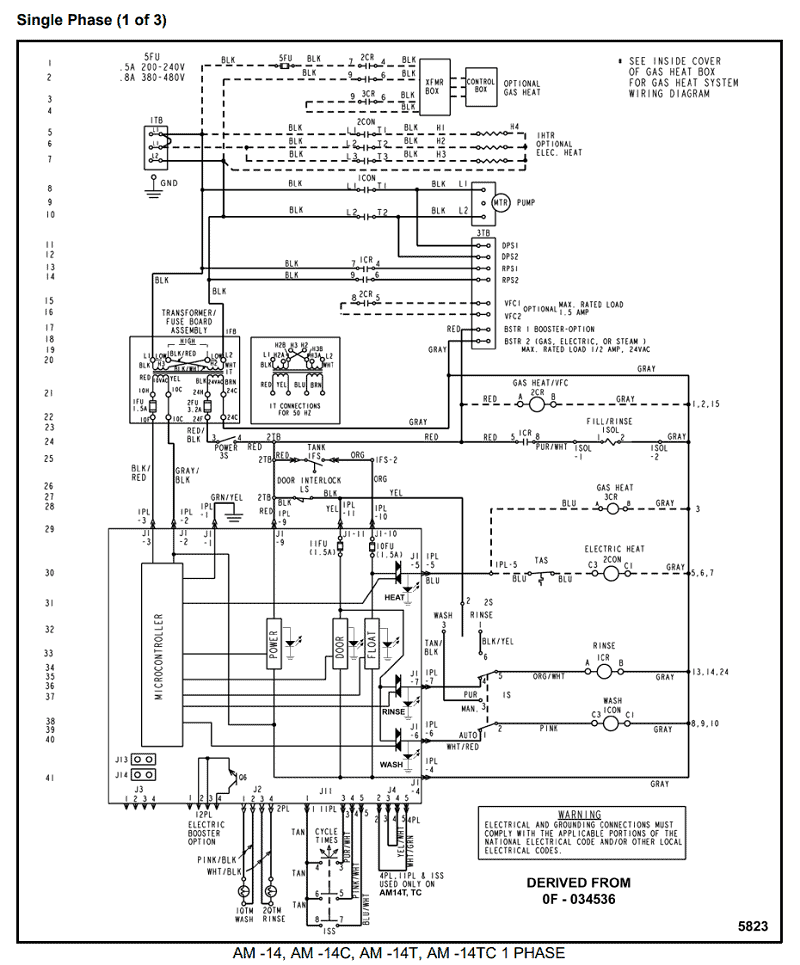
1—MA1A– (A) Air Conditioner Schematic Diagram and Electric Heater Wiring Options v, 1 Phase, 60 Hertz A 5KW 5KW 5KW TOP 2 BANKS. Bard HVAC – Delivering high performance heating and cooling products all over the world.Thermostat Wiring Diagrams – Wire Illustrations for Tstat InstallationElectrical Wiring Diagrams for Air Conditioning Systems – Part One ~ Electrical Knowhow
Understanding HVAC Schematics – 1