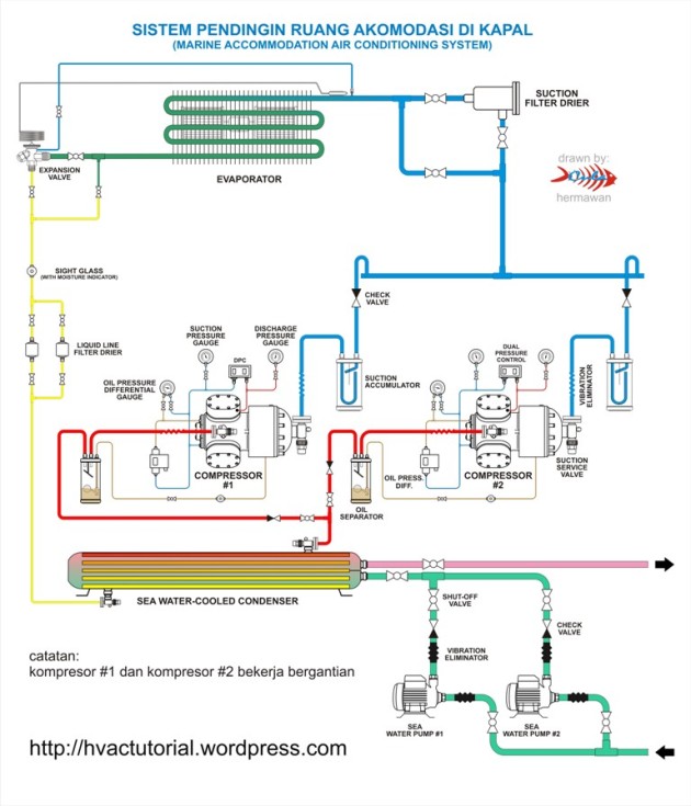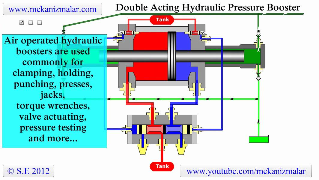
Installation diagram of automatic pump controlled pressurisation unit with pressure Where hydropneumatic tanks are used for storage, the tank is filled to one third to a half Air Compressor Pressure Switch Wiring Diagram Simple Wiring Air.
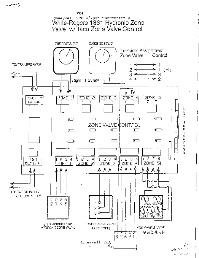
This section specifies a hydropneumatic surge tank complete with control devices , Air Compressor & Control Panel layout, data sheets, schematic diagram and device . House all electrical components including Vent-auto-Add switch.
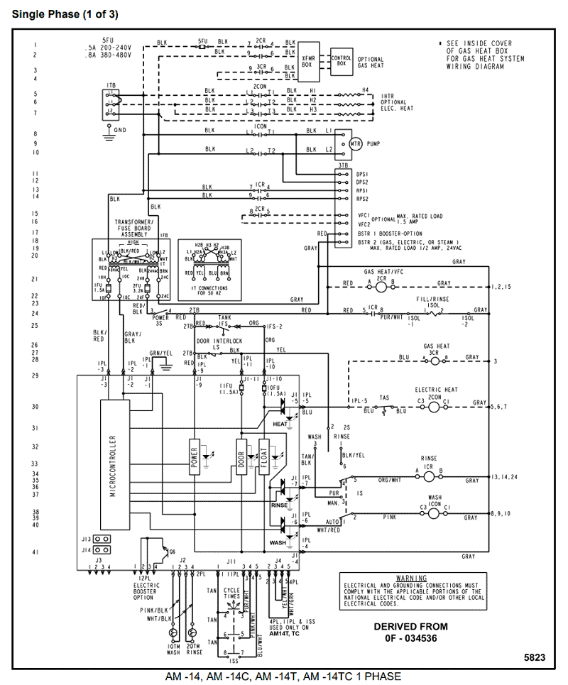
three basic components: an oil-less air compressor, isolated electrode circuit and time delay). and a pressure switch. that it attaches directly to the hydropneumatic tank.
No need to worry .. Harness Assembly v & v ..
Operation is completely automatic and no maintenance is required. The air.
Please fulfil all listed requirements prior to and during installation and operation The water storage tank should provide all the pumps with a fully flooded suction to avoid any air pocket traps and be fitted with at least one positive/ negative automatic air using a car tyre pressure gauge, foot pump or oil free compressor. A wire with an electrode at its lower end extends into the tank through an insulator positioned A check valve in the air compressor exhaust line isolates the air compressor from tank 4 is a schematic wiring diagram of the electrical circuit connected to the water ..
USA Automatic pump control system.Fix your Craftsman Air Compressor today with parts, diagrams, accessories and repair advice from eReplacement Parts! Worldwide shipping, no hassle returns.
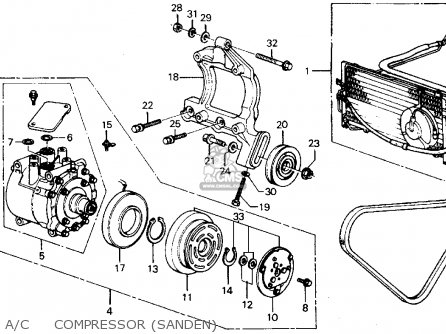
Craftsman Air Compressor Parts Craftsman Automatic Switch Control Storage Tank Compressor Parts. must be installed in accordance with the wiring diagrams in this manual.
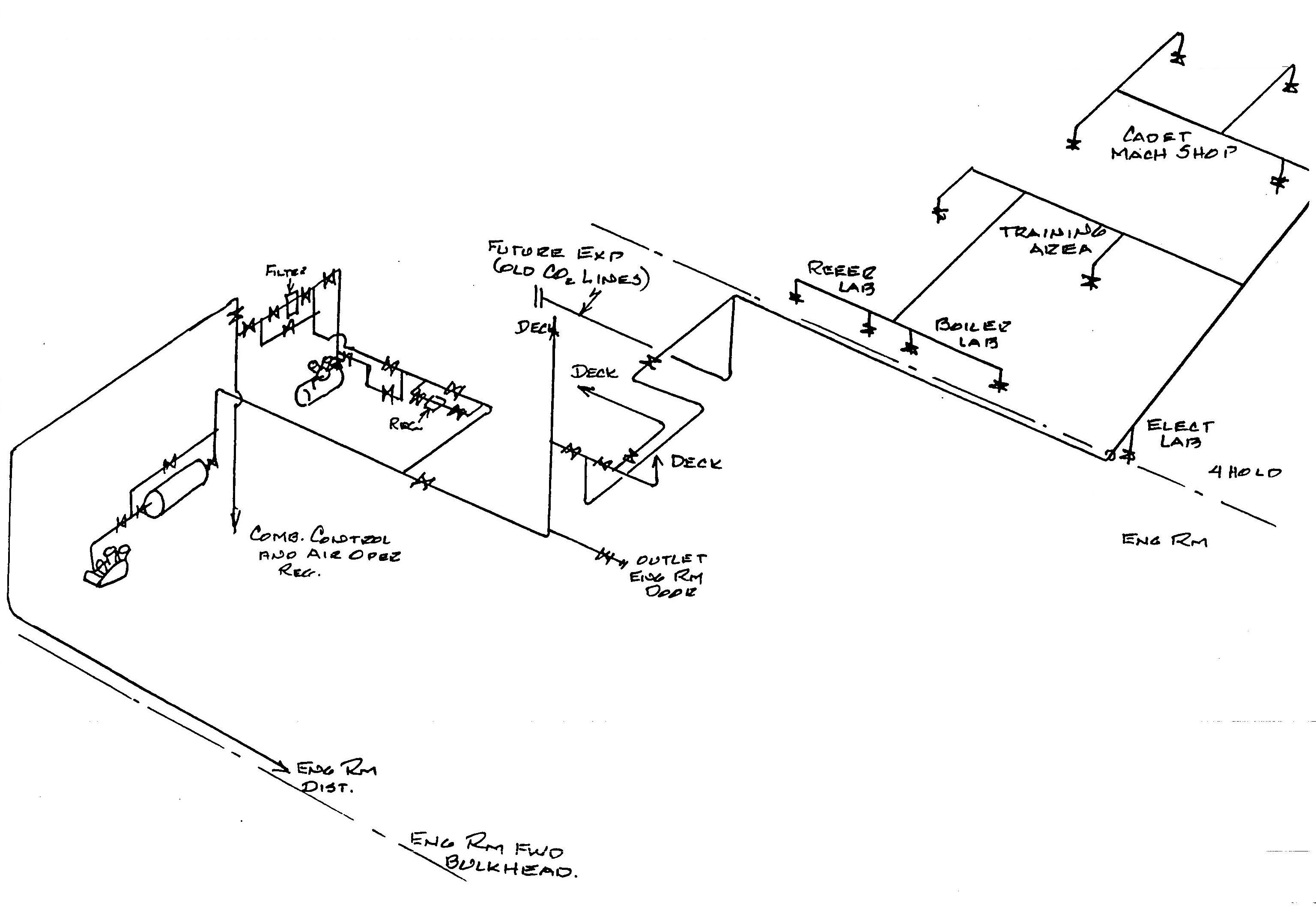
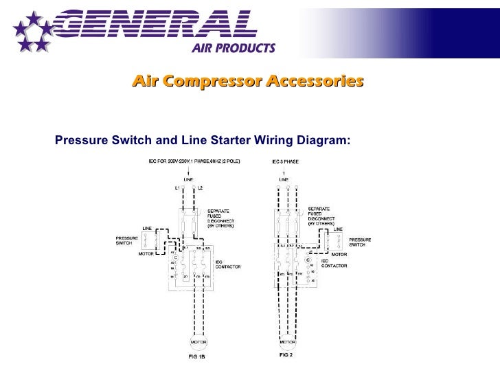
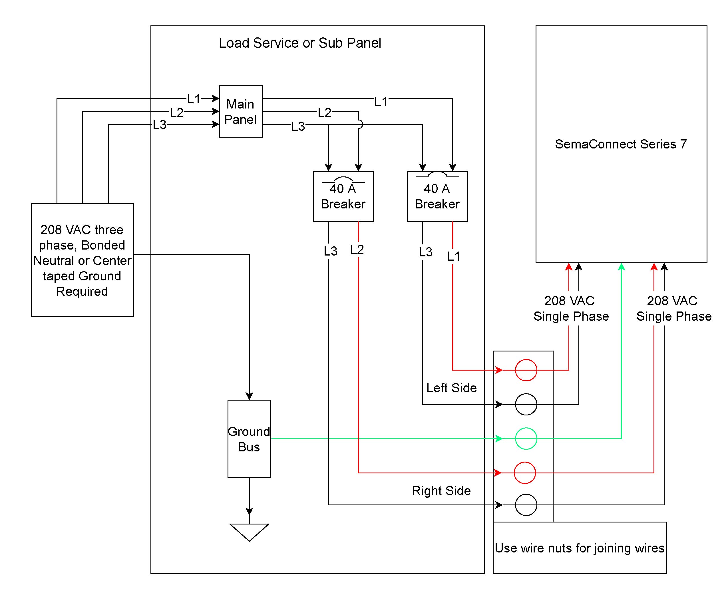
Pressure Switch: If the compressor is NOT equipped with a magnetic starter, refer to the wiring diagram to the right. WIRING DIAGRAM (For units without Magnetic Starters) PRESSURE SWITCH Wire to power source Wire to power source Wire to motor.
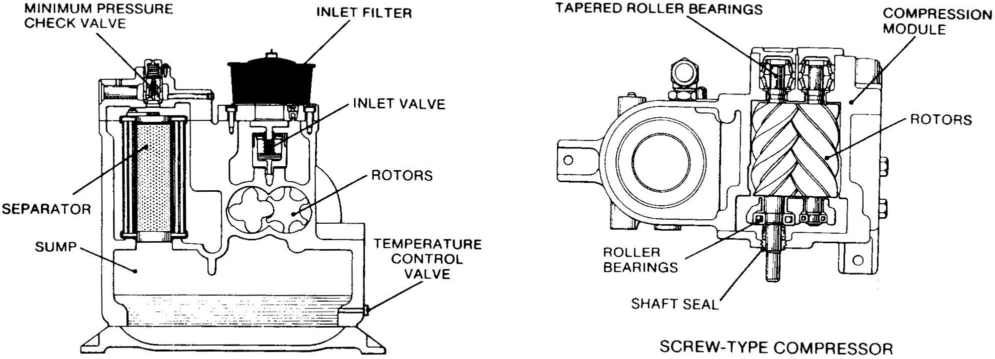
7. Position compressor next to air tank with leader hose partially threaded into check valve. 8.
Mark feet position of both compressor and air tank. 9.
Using these marking, drill holes for mounting. With compressor and tank mounted connect steel leader hose to check valve.

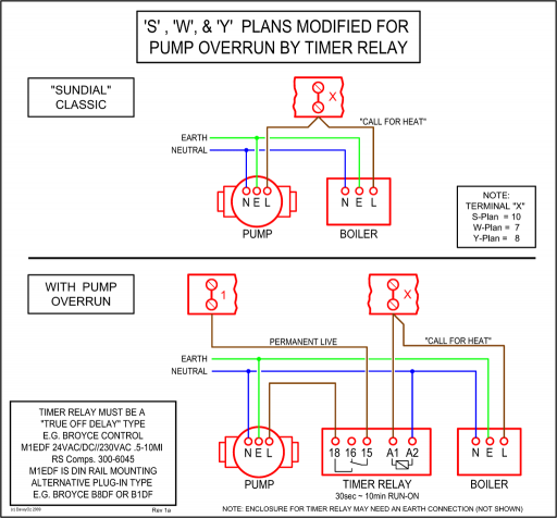
Using diagram mount and wire solenoid and circuit breaker. Hydropneumatic tanks work best with an air cushion of ¼ to ½ the tank capacity.
This cushion decreases as water absorbs air and the tank loses its ability to pressurize the system. To keep that from happening, there must be an automatic way to replenish the air volume.
Adding air manually is not the best way to ensure proper. 1) Compressor Tanks – Because there is a direct air-water interface and the air dissolves into the water this type of tank requires an air compressor and a set of controls to maintain the required amount of air in the Hydro-pneumatic Tank.Pressure Tank Schematic | Wiring LibraryCraftsman Air Compressor Parts | Great Selection | Great Prices | schematron.org
