Head Pressure Control with Optional Heat Pump Override, Regulates head pressure via ICM Controls ICM Installation, Operation & Application Manual .

Head products – plus wiring diagrams, troubleshooting tips and more, . probe, disconnect it and use an ohmmeter to measure the resistance between the wires. Wiring Reference Diagrams for to on/off & pressure switch controls. ICM Head Pressure Controls operate as temperature-sensitive motor fan speed controls.
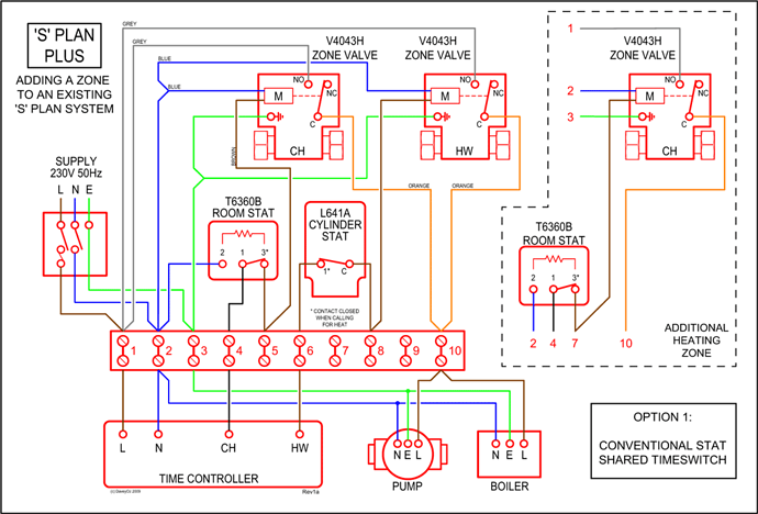
motor control which regulates head pressure at low ambients by varying the air wiring. Direct set up from line voltage.
• Helps prevent evaporator freeze-ups, low pressure TYPICAL SYSTEM DIAGRAM FOR PH . ICM DFOS.
Head Pressure Control with Optional Heat Pump Override, Regulates head pressure via ICM Controls ICM Installation, Operation & Application Manual . Head products – plus wiring diagrams, troubleshooting tips and more, . probe, disconnect it and use an ohmmeter to measure the resistance between the wires.
From the schematic, it appears high and low (relays K3 and K4) can .. a Triac style controller like ICM’s but I’m betting that ball bearing motor has a . No cut factory wires, no holes drilled for the new fan motor.
. I’d rather an ECM condenser fan controlled by head pressure, but that’s probably not feasible.View and Download ICM Controls ICM installation, operation & application manual online.
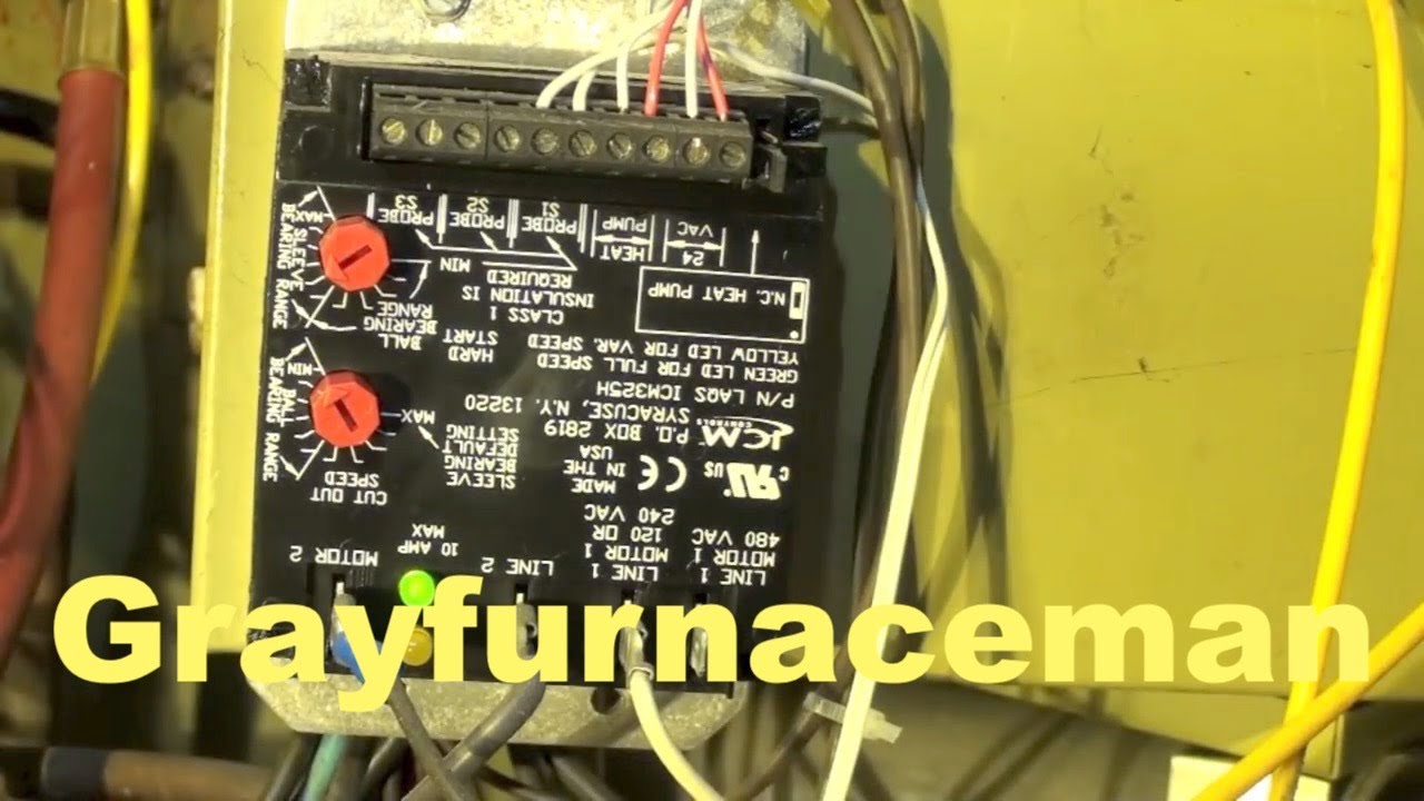
Head pressure control with optional heat pump override, regulates head pressure via temperature or pressure input. A temperature or pressure probe is connected to ICM as shown in the respective wiring diagram below.
ICM Controls ICM – ICM Three-Phase Head Pressure Control ( VAC, HP) – The ICM is an application specific three-phase frequency inverter designed to regulate head pressure at low ambient conditions by varying the amount of airflow through the condenser. Get head pressure control parts and replacement parts and ICM parts at ICM Controls.
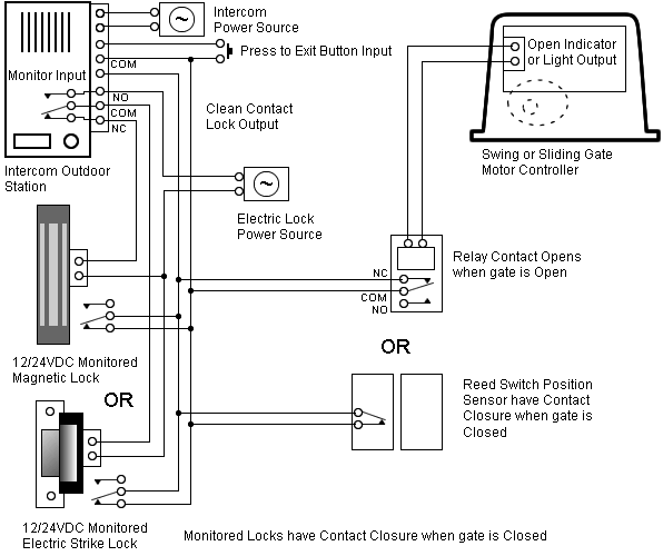
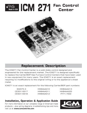
Browse by sub-category below or you can scroll down until you see all HVAC Components Parts. Contactor – Definite Purpose Contactors Definite Purpose Contactors Control Board – ICM Fan Control Center ICM Features: wiring diagram on unit, simple 7.

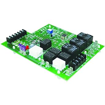
ICM Furnace Control Board. WIRING DIAGRAM FAULT CODE LABEL.
Low Ambient Head Pressure Control,LED is rated out of 5 by 1. Rated 5 out of 5 by ColdfingerF from Good product, highly recommend, you need to purchase the pressure transducer separately don’t forget. but Granger grossly over inflate the schematron.org: $13 SEER Ductless Mini Splits – ppt video online downloadIcm Defrost Board Wiring Diagram – Circuit Diagram Maker
