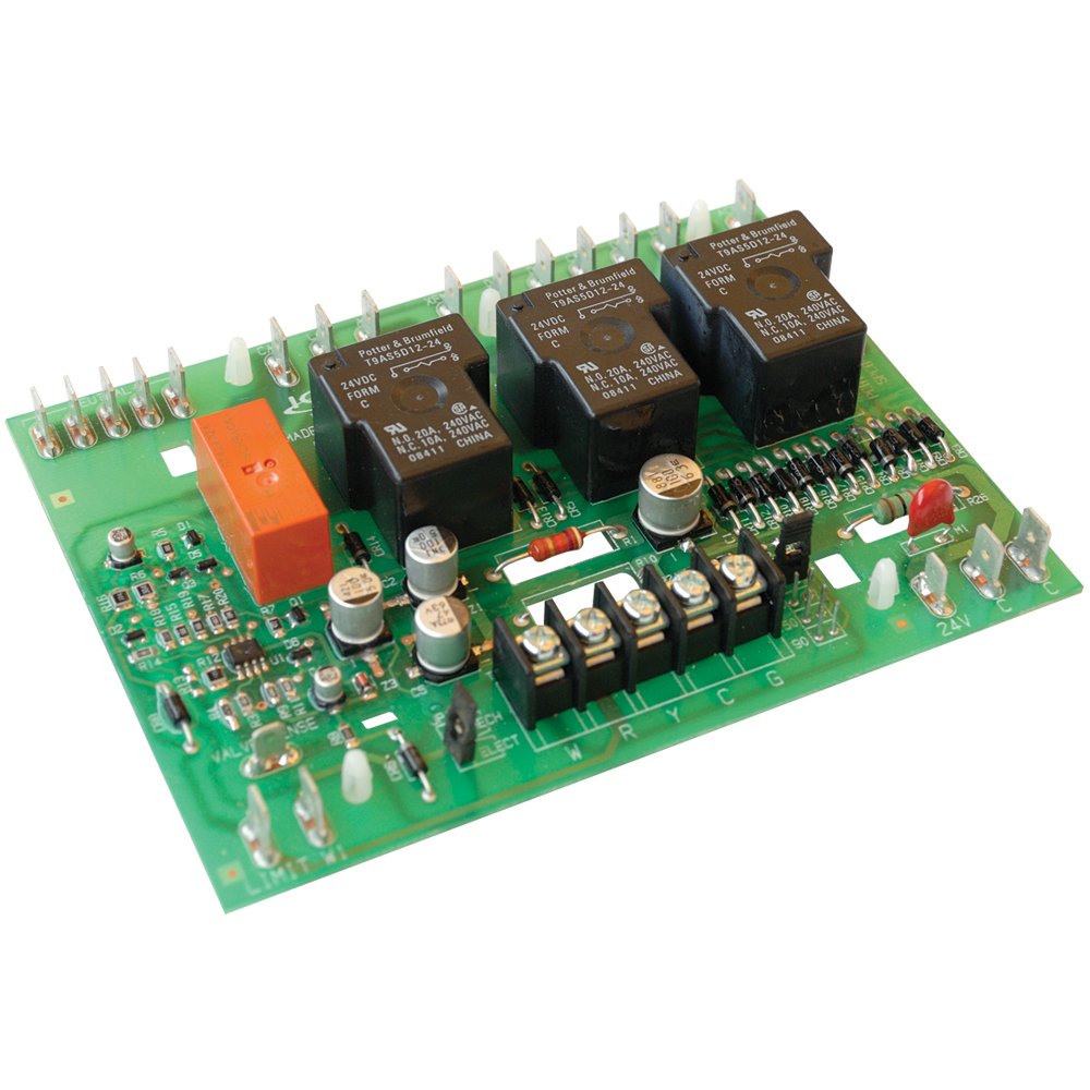
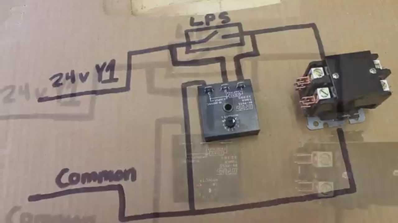
The lockout relay circuit
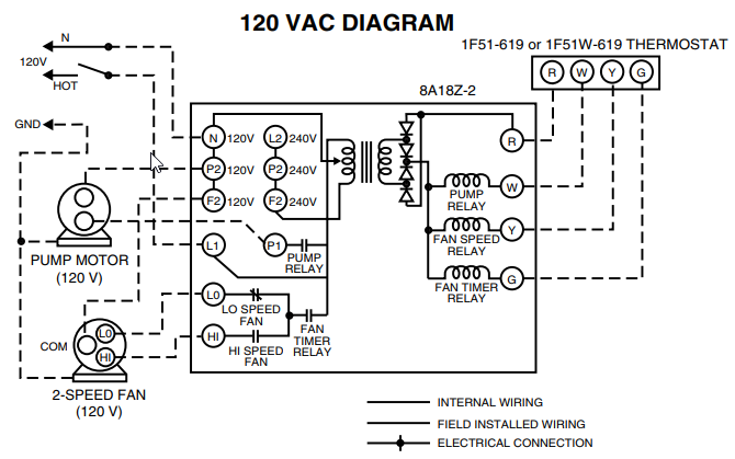
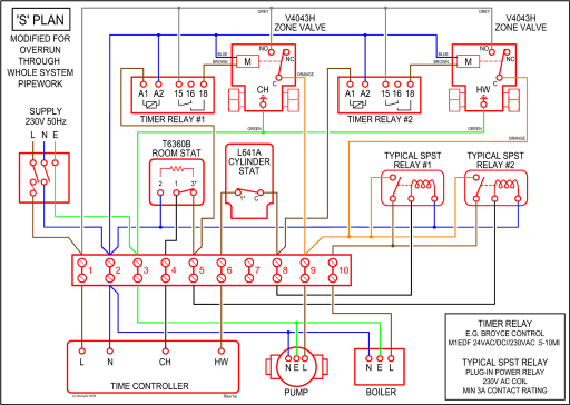
wiring diagram below. 3.
Time Delay on break for compressor
Select desired time delay. (adjustable models only).
A/C Air Conditioning, Refrigeration and Heat Pump Delay-on-Break Timer – Part# ICM203
4. Reapply power, check operation. MODE OF OPERATION.
With application of. Non-Programmable Thermostats. New Construction.
Diagrams. Accessories. 4.

8 . 14 ICM’s line voltage monitors were specifically .
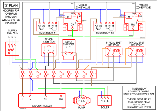
Control circuit wires. Ideal for “winterstart” kits.
Central Air Conditioning System will not cool house part 1
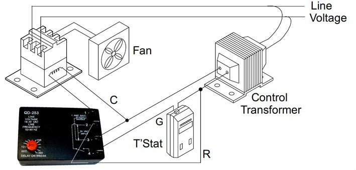
WIRING DIAGRAM. Input Time Delay.
• , seconds. TIMING DIAGRAM ICM CONTROLS. schematron.orgtrols.
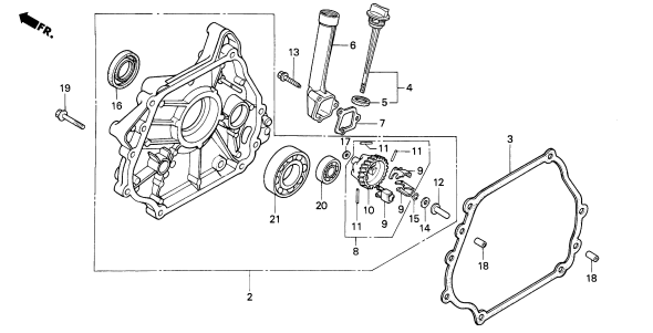
2. Connect terminals as shown in the wiring diagram below.
3. Select desired delay on break period.
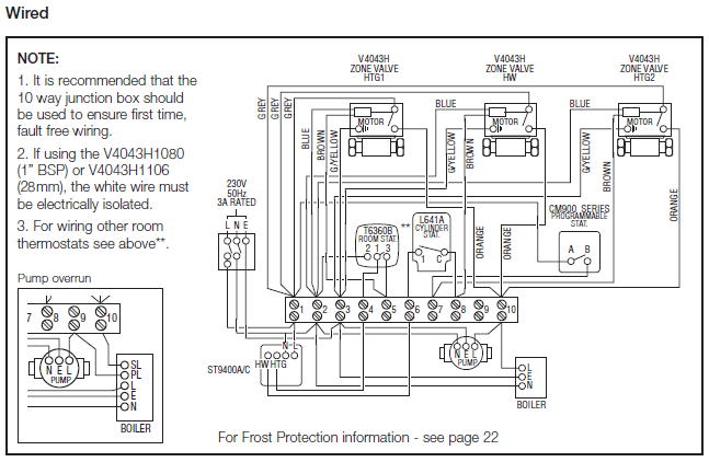
4. Reapply power, check operation.
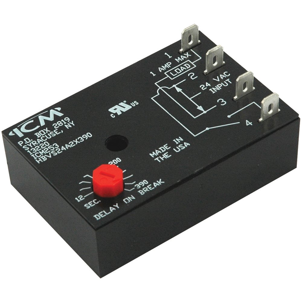
MODE OF OPERATION. Non-Programmable Thermostats. New Construction.
Diagrams. Accessories.
A/C Air Conditioning, Refrigeration and Heat Pump Delay-on-Break Timer – Part# ICM203
4. 8 .
14 ICM’s line voltage monitors were specifically . Control circuit wires.Mode of Operation – ICM Head Pressure Controls operate as temperature-sensitive motor fan speed controls.
Head pressure is regulated during low ambient conditions by varying the amount of airflow through the condenser. Find best value and selection for your ICM LR AA FHP P N Lock Out Relay search on eBay.
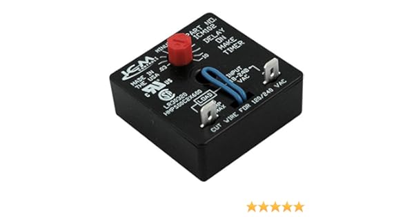
World’s leading marketplace. wiring diagram below.
3. Select desired delay on break period.
4. Reapply power, check operation.
MODE OF OPERATION Power must be applied before and during the time delay period. When the initiate contact ICM CONTROLS schematron.org LII TIMING DIAGRAM.
View and Download ICM Controls SC installation, operation & application manual online. Non-Programmable Electronic Thermostats. SC Thermostat pdf manual download. ICM’s series Interrupted-duty Ignition Oil Primary Controls offers the basica control of the functions of the ICM series – including the patented energy transfer technology for added safety – with Interuppted Ignition for extended life and various post purge time delays.ICM Bypass Timer from ICM Controls, North Syracuse, NY | Proudly Made-in-AmericaICM Lockout Relay from ICM Controls, North Syracuse, NY | Proudly Made-in-America
