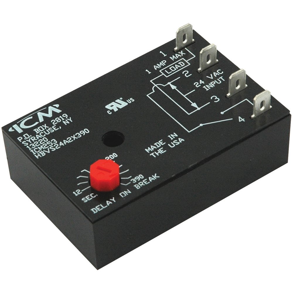
plus wiring diagrams, troubleshooting tips and more, visit us at ICM Honeywell: SA ICM MARS: , , ICM The manufacturer’s documentation is one small, folded piece of paper with a wiring diagram, brief general installation wording, and a brief mode of operation.
Some local codes require licensed installation/service personnel for this type of equipment. Read all ..
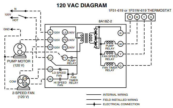
Wiring Diagram • 5 Wire Heating/Cooling Thermostat. 9.
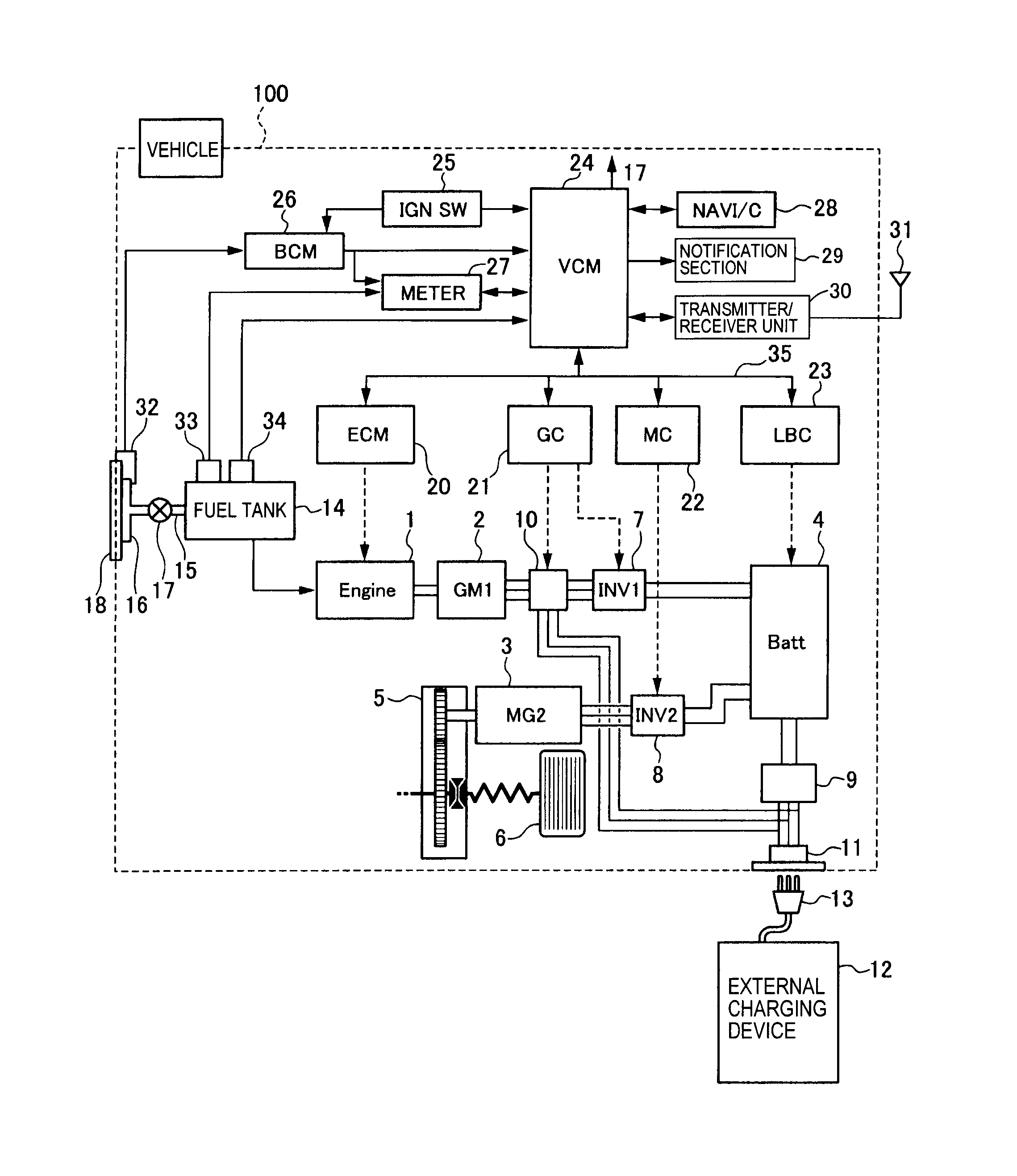
icm lr relay moreover icm along with icm also with icm also with ON delay timer diagram 22 how to wire dayton off delay timer icm INSTALLATION. 1.
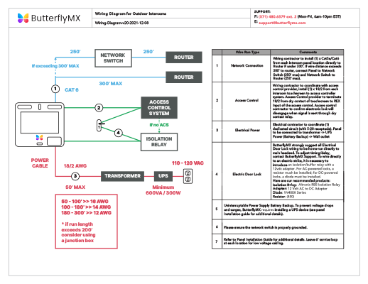
Disconnect power. 2.
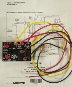
Connect terminals as shown in the wiring diagram below. 3.
Select desired delay on make and delay on break periods.ICM Controls ICM – ICM Delay on Break Timer Minute Knob Adjust. Delay) – Delay on Break Timers (“anti-short cycle”, “ON delay on break”) helps to protect air conditioning, refrigeration and heat pump equipment from damage which may be caused by the rapid short cycling of compressors.
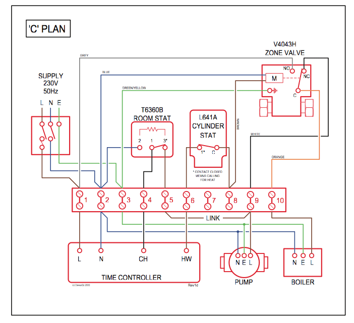
Mode of Operation – Upon application power, the load is energized. A wiring diagram is a simple visual representation of the physical connections and physical layout of an electrical system or circuit. It shows how the electrical wires are interconnected and can also show where fixtures and components may be connected to the system.
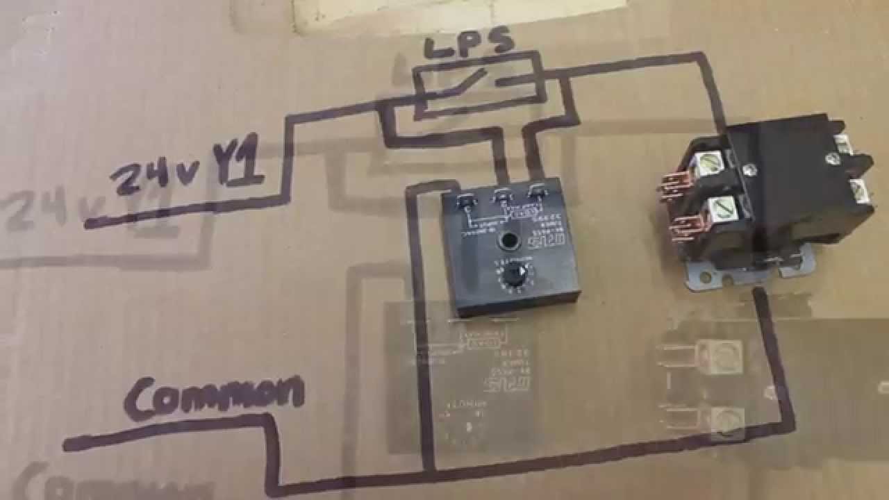
Feb 15, · The low voltage wire from the thermostat g to the old relay coil should be able to connect to g on your ICM board and common from the transformer secondary to the old relay to . wiring diagram below.
3. Select desired delay on break period. 4.
Reapply power, check operation. MODE OF OPERATION Power must be applied before and during the time delay period.
When the initiate contact closes, the load energizes and remains energized as long as the initiate contact is closed. The green wire on the thermostat feeds that relay, so if you go to the furnace and shut the power off and find the green wire from the thermostat that feeds that relay and replace it, being careful to mark all the wires before removing them, also the relay terminals have numbers for identification.NORDYNE MAC Furnace Fan Limit Switch ICM ICM | eBayHow to wire ICM in place of Blower Relay For Bryant – Fixya
