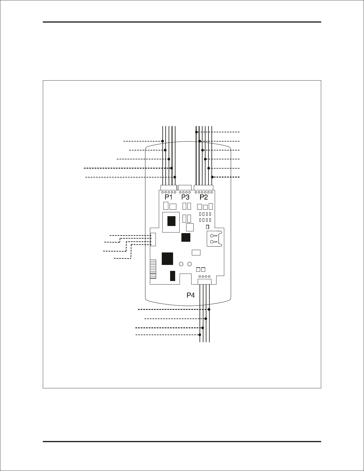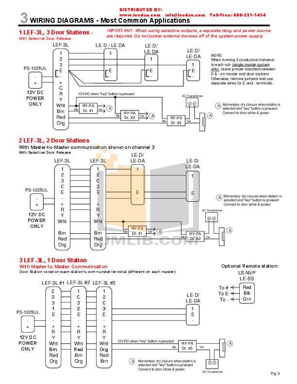
Keypad Wiring Diagram On Download Wirning webtor me.
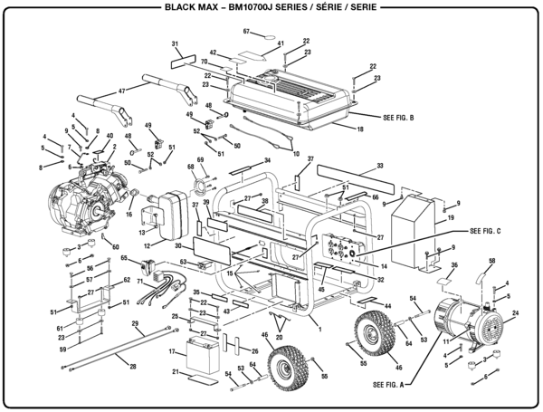
November 15th, – keypad wiring diagram iei i programming diagrams. the keypad housing.
IEI recommends using a filtered and regulated power supply . When mounting the w outside, use a weatherproof back box and apply. DOOR♢GARD COMMAND AND CONTROL SERIES keypads offer field proven reliability and cost See the Wiring Diagram and Specifications for the relay.
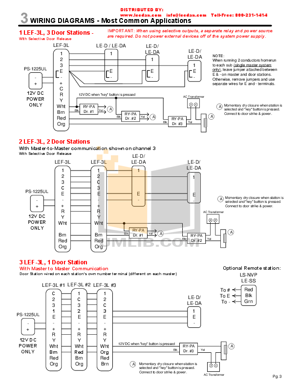
Stand Alone Keypad-Installation Manual. Features: ❖ User . Example of wiring to an IEI request to exit device (part # EZ-REX).
Wiring the Bell Button. i Wiring Diagrams LIT I/W SMT WIRING INSTRUCT – P/N: X2 – INK: BLACK keypad, when using an electrical locking device, you MUST.Iei keypad wiring diagram unique of with iei se keypad wiring diagram electrical diagrams to maglock i keypad wiring diagram diagrams and iei kwikpik me for image 7 3 glow plug relay wiring diagram save lutron rh jasonaparicio co iei keyp ra2 new.
e & eM Keypad Installation & Programming Circuit Board Diagram Main Wire Harness (P2) Secured Series Front End Wiring Diagram To use the keypad as a Secured Series Front End, connect the red, black, white/black and white/yellow wires, on the main keypad wire e & eM Keypad Installation & Programming. i Wiring Diagrams The diagram above shows how to connect two keypads to control a single door.
Entering your code on keypad 2 unlocks the maglock directly. When you enter your code on keypad 1, it triggers the REX input of keypad two, which unlocks the door Please note that user codes must be programmed into both keypads.
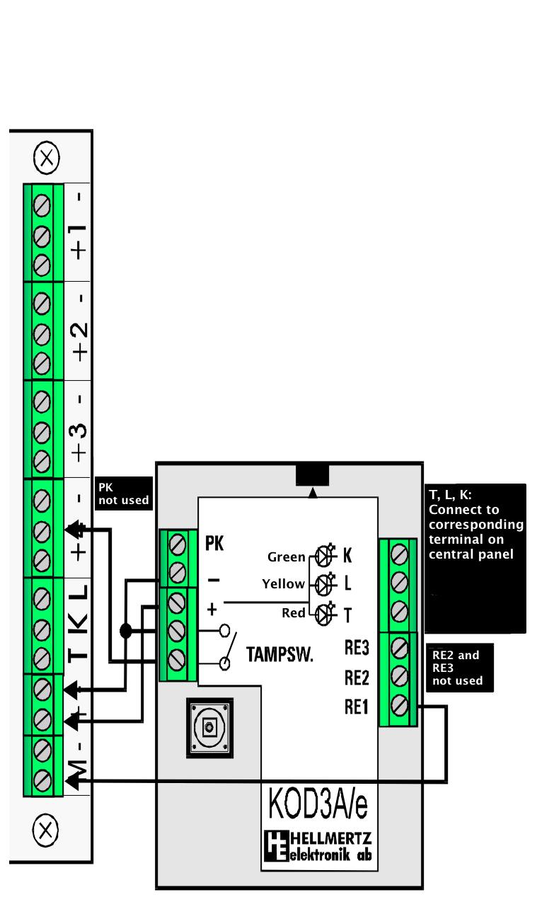
Document # X2 Page 1 of 32 IEI schematron.org™ Proximity Reader/Keypad Access Control Installer Guide Now Part of This Installer Guide is designed as a reference document for . Secured Series Front End Wiring Diagram To use the keypad as a Secured Series Front End, connect the red, black, white/black and white/yellow wires, on the main keypad wire harness, to the corresponding terminals on the Secured Series Door Control Module. The drain wire must be .Iei i Keypad Wiring Diagram | Wiring LibraryIei i Keypads Wiring Diagram | Wiring Library
