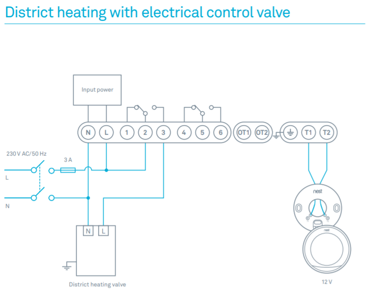
WIRING INSTRUCTIONS: To wire switch follow diagram above. Use solid or stranded COPPER INTERMATIC INCORPORATED.
Wiring Diagrams
SPRING GROVE, ILLINOIS. This Pin was discovered by Fuyang Ke. Discover (and save!) your own Pins on Pinterest.
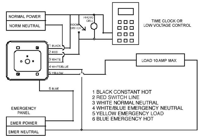
Timer wiring. How To Wire and Connect A Intermatic Pool Pump Timer – TR . Chargèro. Loading Unsubscribe from Chargèro? Cancel. *Can be wired SPDT. **Separate Clock Motor Terminals.
T104 Wiring begins here
T T Series schematron.org Energy Controls. Diagrams. T Series.
Specification. Use T Volt timer to control 3 phase loads. use wiring diagram above to control 3-pole contactor, or diagrams to left and right.
T104 Wiring begins here
Neutrals connect to terminal .intermatic incorporated ts spring grove, illinois time pointer time dial off tripper manual lever on tripper clock motor ground a 1 2 grd. v supply to line load neut. wiring diagram pressure plate terminal screw make sure wire insulation clears pressure plate minimum copper wire size (awg) max.
load (amp) min. insul-ation. WIRING DIAGRAM WARNING Risk of Fire or Electric Shock • Disconnect power at the circuit breaker(s) or disconnect switch(es) before installing or servicing.
• Installation and/or wiring must be in accordance with national and local electrical code requirements. • Use wires rated at least 90°C – COPPER conductors ONLY.
I need installation or wiring diagram for Timer Intermatic T101
Browse Intermatic’s General Catalog, Pool & Spa Catalog, Grasslin Catalog, and Specification Guide. View Instruction Manuals, Wiring Diagrams, Product Brochures and Sell Sheets. Watch How-To instruction videos. Search our new and improved Image Library for images of Intermatic Products.
Intermatic T101 Supplementary Manual
How To Install an Intermatic T Timer A major difference between the T and T timers that you have to consider is the timer motor. The T runs on V; the T runs on V. In the wiring diagram is says neutral.. when I connect it to the white neutral bar in the fuse box it trips the gfi same if I connect it to the ground. Jun 24, · How to Replace an Intermatic TM V ( V) Pool Timer – Duration: Swimming Pool Tips, Reviews & How To -MrDgvb1 , views.How to wire Intermatic T and T and T timersHow To Install an Intermatic T Timer – schematron.org
