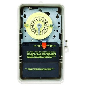
These heavy-duty Mechanical Time Switches are designed for commercial, industrial and residential applications and have the highest motor load ratings in the. WEBSITE: schematron.org YouTube Video Index — A list of all of my videos.
WIRING INSTRUCTIONS: To wire switch follow diagram above. Use solid or stranded COPPER only wire with insulation to suit installation. See gauge selection.

When you open the enclosure door, there is translucent or solid black insulator covering the wiring. As long as insulator is in place, it is safe to touch visible timer . Connect your incoming line) volt wires to terminals #1 and 3.
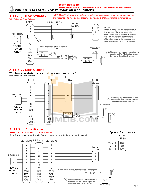
Connect the outgoing volt (load) wires to terminals # 2 and 4. Don’t forget.Subscribe to Our Newsletter Sign-up for email alerts for products and software updates, new product releases and information about upcoming events. Nov 12, · You know that the Intermatic wire order so it is just a matter of matching the wires up as the other timer may not have the wires all in the same location as the Intermatic one here.

This heavy duty Intermatic TP3 pool/spa mechanical time switch is designed for industrial, commercial, and residential applications and has the highest motor load ratings in the industry. The unit provides up to 12 ON/OFF operations each day with a minimum ON/OFF time of one schematron.org: When wiring, be sure to follow local and NEC/CEC electrical codes. In the wiring diagram is says neutral..
when I connect it to the white neutral bar in the fuse box it trips the gfi same if I connect it to the ground bar this is a double pole switch with GFI. How To Install an Intermatic T Timer Most Popular. Swimming Pool.
Intermatic makes a freeze protection control that wires directly into a V timer. If you already have a freeze control, the wiring diagram might help.
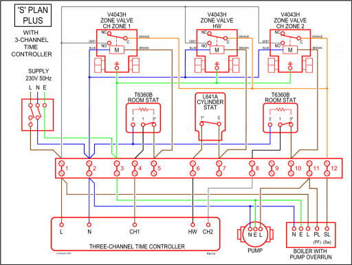
The manual has this image larger. It shows wiring to connect the freeze control directly to one V timer. Intermatic make a freeze control for 1 or 2 circuits.How to wire Intermatic T and T and T timersSOLVED: Need wiring diagram for Intermatic V Mechanical – Fixya
