
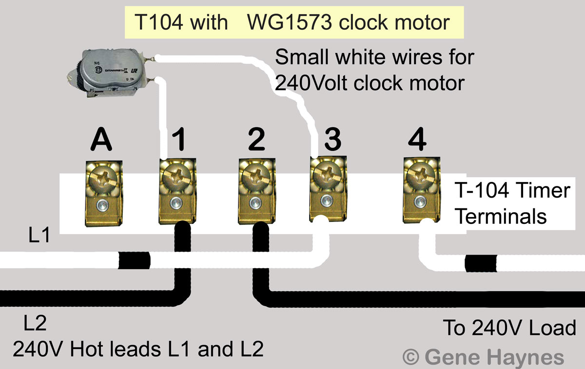
LINE 2. / VOLT CONNECT MOTOR LEADS TO TERMINALS.
“A” AND 1 AND SUPPLY NEUTRAL TO TERMINAL “A”. WIRING.
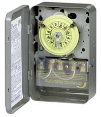
DIAGRAM. V 2 WIRE.
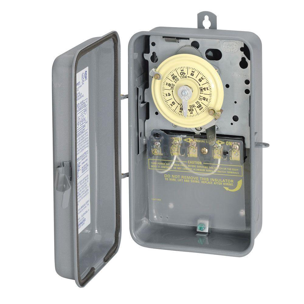
The T Series Mechanical Time Switch has proven it can stand the test of time. These dependable time switches can handle electrical loads up to 40 A per.
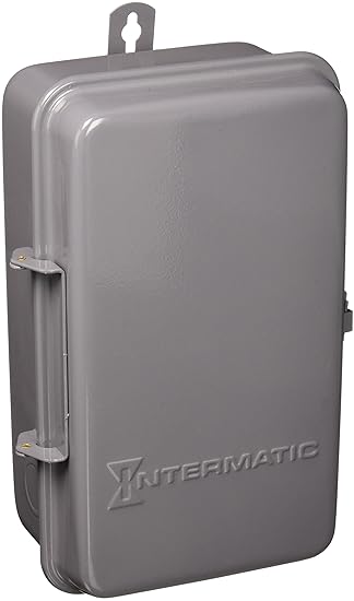
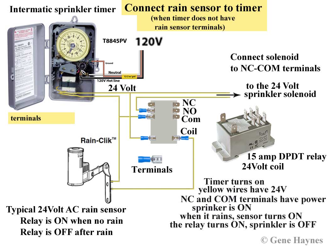
Is clock motor WG? Intermatic T Basic wiring diagram, T timer Volts or Volts Check label on side of water heater for Volts & Watts This timer.
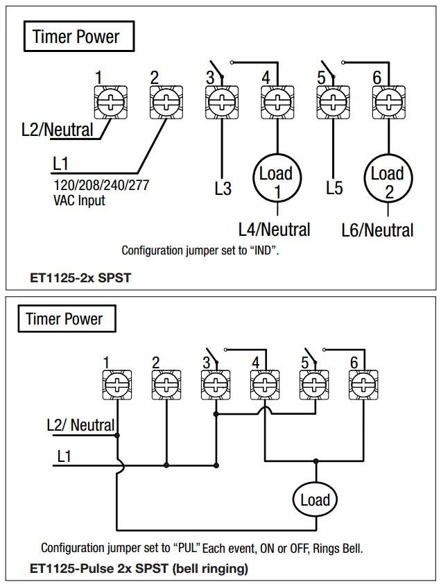
The T Series mechanical time switch has proven it can stand the test of time. These dependable time switches can handle electrical loads up to 40 A per.
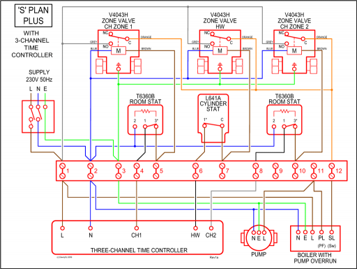
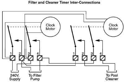
WIRING INSTRUCTIONS: To wire switch follow diagram above. Use solid or stranded COPPER INTERMATIC INCORPORATED.
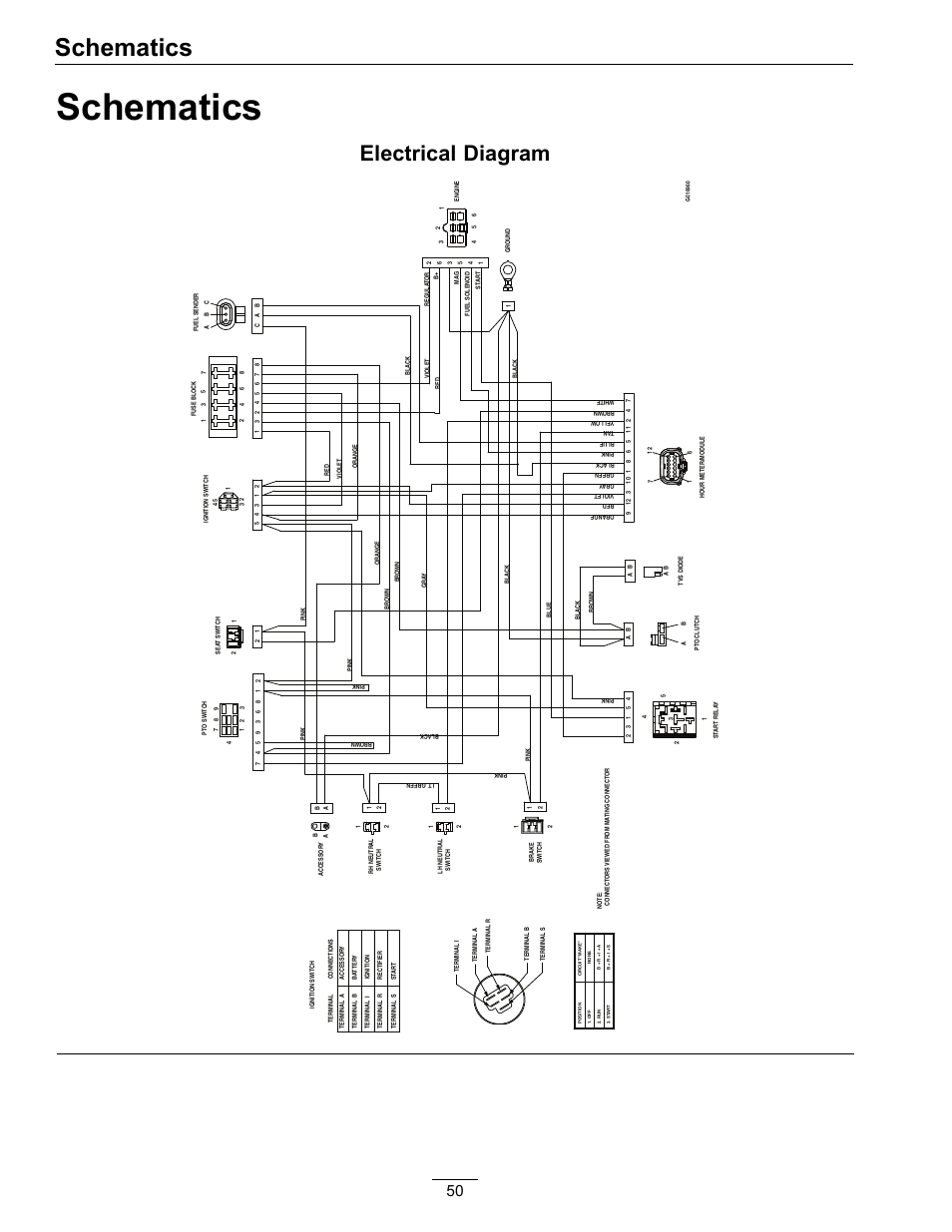
SPRING GROVE, ILLINOIS.INT-MAT TR DPST V MECH | Gordon Electric Supply, Inc+ followers on Twitter. WIRING INSTRUCTIONS: To wire switch follow diagram above. Use solid or stranded COPPER only wire with insulation to suit installation.
See gauge selection table for normal service applica-tions. To make power connections remove 1/2 inch of insulation from wire ends/5(2K).
Wiring intermatic TR timer [ 6 Answers ] Hi everybody! I work as a handyman.
While trying to install an intermatic tr timer, I found that th E clock does not work. I believe I followed the diagram.
Manually It works, but I do not hear the clock ticking. Is it supposed to?.
Wiring intermatic TR timer [ 6 Answers ] Hi everybody! I work as a handyman.
While trying to install an intermatic tr timer, I found that th E clock does not work. I believe I followed the diagram.
Manually It works, but I do not hear the clock ticking. Is it supposed to?. WIRING INSTRUCTIONS: To wire switch follow diagram above.
Use solid or stranded COPPER only wire with insulation to suit installation. See gauge selection table for normal service applica-tions. To make power connections remove 1/2 inch of insulation from wire ends.
Insert bare ends of wire under the pressure plate of terminals.How to wire Intermatic T and T and T timersWiring for a TR Timer