Time Switches and Controls · Sensors · HVACR Solutions · Power Protection Duo · Timers · Hour Meters · Surge Protective Devices · Weatherproof Receptacle. The timers have an Astronomic feature for sunrise and sunset switching. Videos.
Intermatic ST01C Single Pole Time Switch Installation · Intermatic ST01C 3-Way . INTERMATIC.
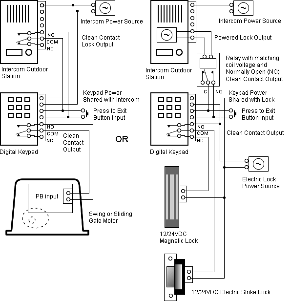
SPRING WOUND INTERVAL TIMER. INSTALLATION INSTRUCTIONS: This spring wound timer is as easy to install as a light switch in a standard.
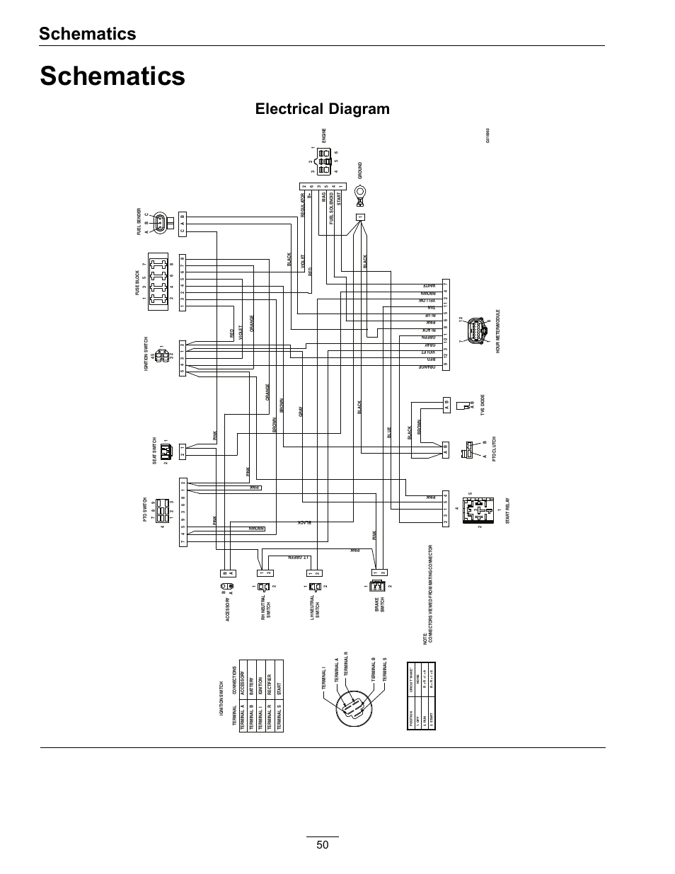
the timer. THE RED TIMER WIRE IS NOT USED FOR SIN-.
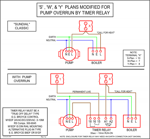
GLE SWITCH INSTALLATIONS. See “Other Installations” on the next page for wiring diagrams for new ..
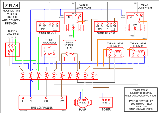
in material or workmanship, Intermatic Incorporated will repair or replace it. Running pool equipment 24 hours is usually unnecessary and expensive.
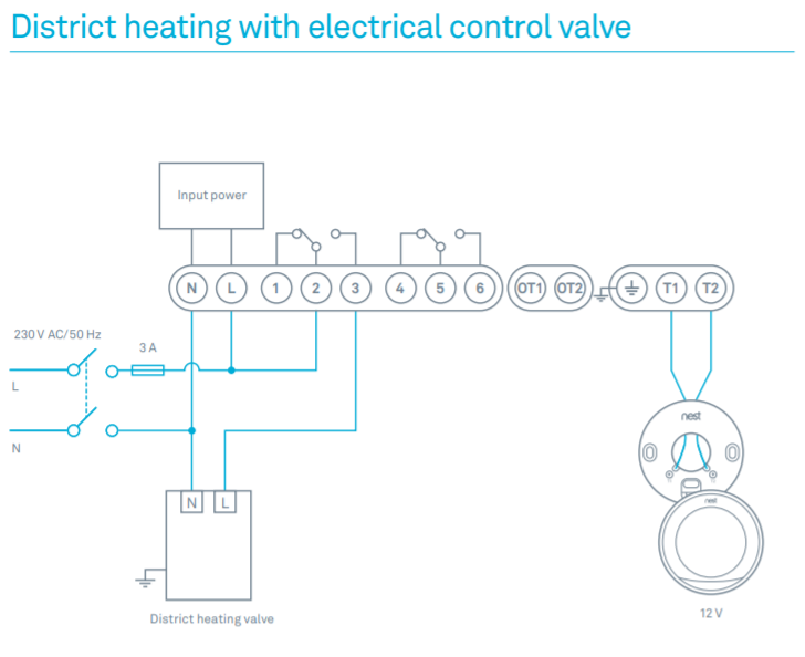
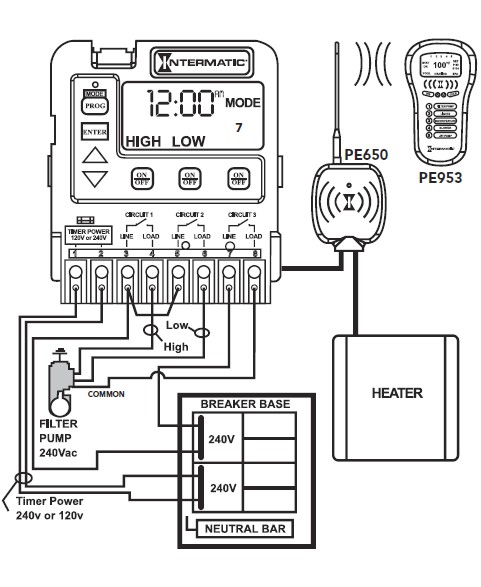
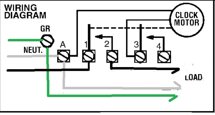
Installing an Intermatic T timer is a great way to dramatically reduce run time and.Isolated switch allows timer to be used with any load type, including AC and DC loads Replaceable CR2 lithium battery provides up to three years of operation No neutral wire connection enables easy retrofitting and quicker installation. Wiring Instructions for an Intermatic Timer.
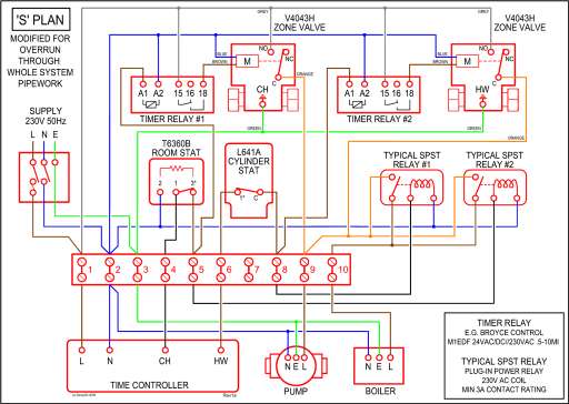
Intermatic Incorporated manufactures timer switches designed for indoor and outdoor use. Many pool pump motors and water heaters use Intermatic timers to regulate their run times.
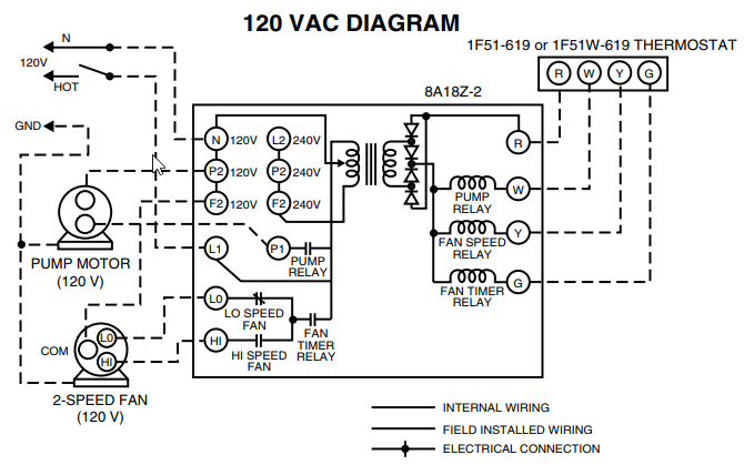
An Intermatic timer-switch saves electricity when it turns a water heater off at night and when it limits the amount of time. Jun 13, · How to connect Intermatic T timer (with diagram) – Answered by a verified Electronics Technician We use cookies to give you the best possible experience on our website.
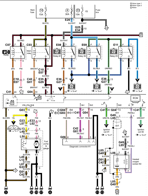
By continuing to use this site you consent to the use of cookies on your device as described in our cookie policy unless you have disabled them.5/5. Browse Intermatic’s General Catalog, Pool & Spa Catalog, Grasslin Catalog, and Specification Guide.

View Instruction Manuals, Wiring Diagrams, Product Brochures and Sell Sheets. Watch How-To instruction videos. Search our new and improved Image Library for images of Intermatic Products.
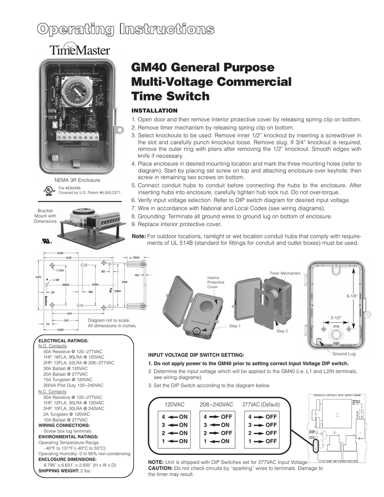
Jun 30, · The timer works, just not the switch. At first I thought I had a bad timer and bought a new one to replace it.
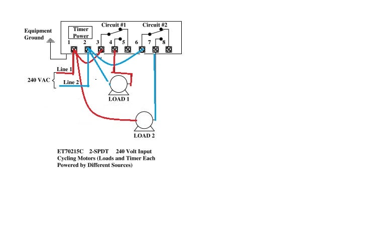
The same behavior was happening on the new one as the old one. I recently had an electrician replace the conduit going from the pump to the timer.
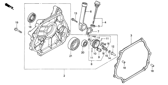
I am now thinking maybe he did not wire it correctly. I have a R Intermatic which is.ST01 – IntermaticPureLine Pool Salt System 20, Gallons – PL – schematron.org
