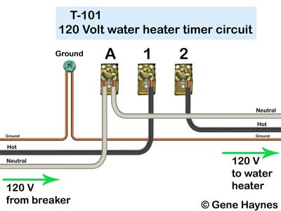
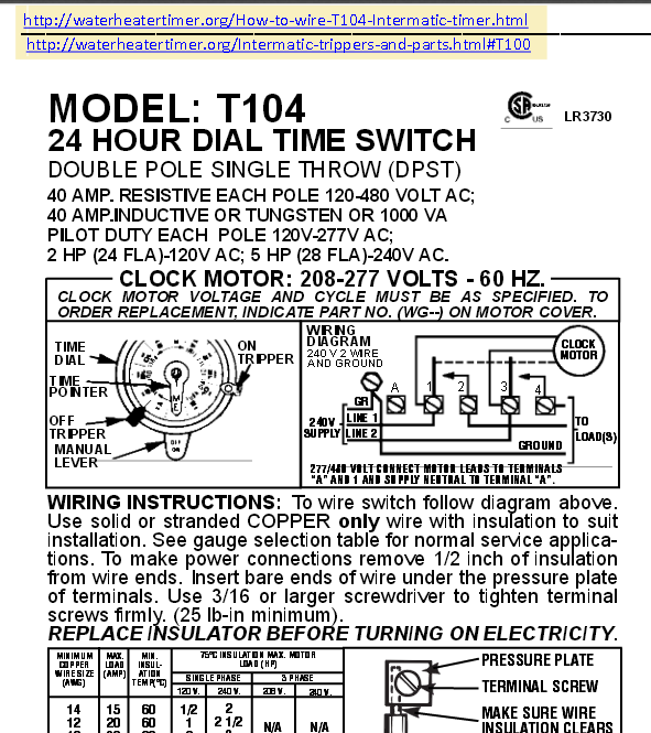
If you are using V supply voltage, you will need a T timer. Connect the ground wire to the green screw located on the Intermatic timer mechanism.
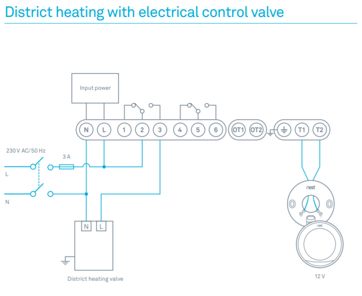
WIRING. DIAGRAM. WARNING Risk of Fire or Electric Shock.
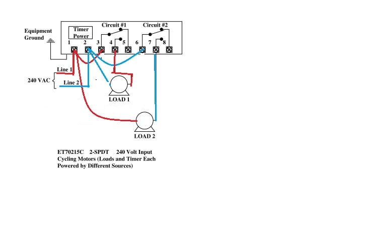
• Disconnect power at the circuit breaker(s) or Moving the clock hands can damage the timer. The Intermatic® line of occupancy sensors are engineered and tested for and only allows defrosting when necessary at the next programmed timer interval.

If you are using V supply voltage, you will need a T timer. Connect the ground wire to the green screw located on the Intermatic timer mechanism.
Copy following link for Volt T timer wiring options: http://waterheatertimer. org/schematron.org#T If you need.Browse Intermatic’s General Catalog, Pool & Spa Catalog, Grasslin Catalog, and Specification Guide. View Instruction Manuals, Wiring Diagrams, Product Brochures and Sell Sheets.
Watch How-To instruction videos. Search our new and improved Image Library for images of Intermatic Products.
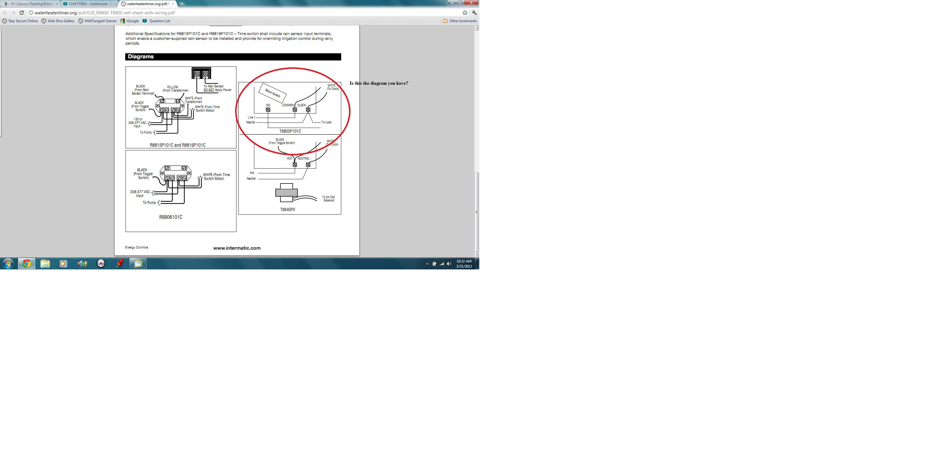
Jun 13, · How to connect Intermatic T timer (with diagram) – Answered by a verified Electronics Technician We use cookies to give you the best possible experience on our website. By continuing to use this site you consent to the use of cookies on your device as described in our cookie policy unless you have disabled them.5/5.
Intermatic T Supplementary Manual. 24 hour dial time switch.
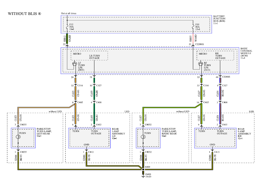
WIRING INSTRUCTIONS: To wire switch follow diagram above. Use solid or stranded COPPER only wire with insulation to suit. installation.
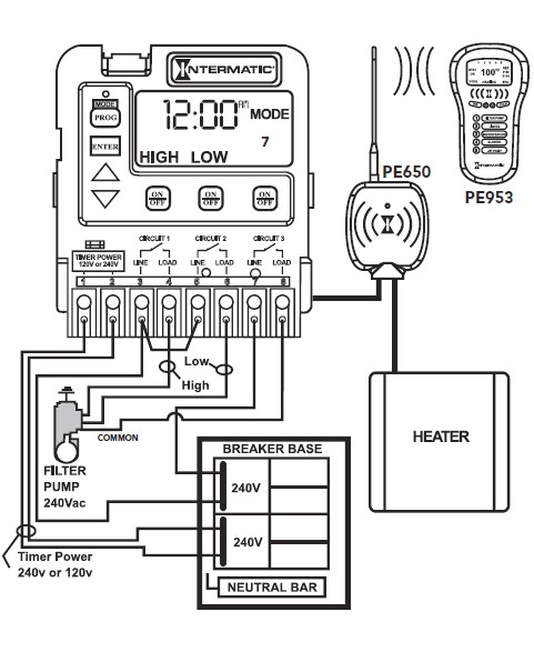
See gauge selection table for normal service applica- Intermatic etc time . Wiring Instructions for an Intermatic Timer.

Intermatic Incorporated manufactures timer switches designed for indoor and outdoor use. Many pool pump motors and water heaters use Intermatic timers to regulate their run times.
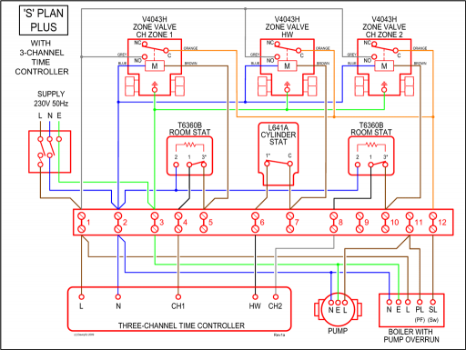
An Intermatic timer-switch saves electricity when it turns a water heater off at night and when it limits the amount of time. proper time-of-day.
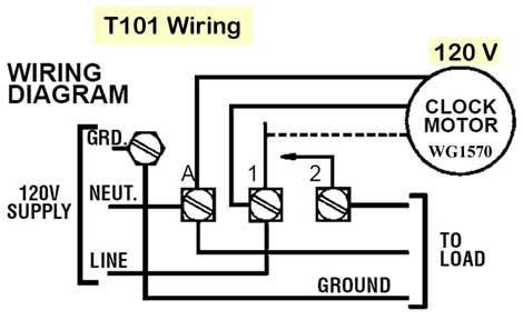
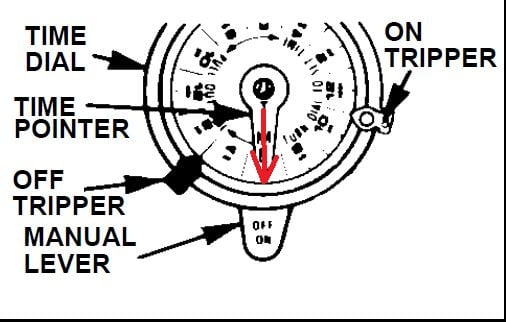
see programming instructions. intermatic incorporated ts spring grove, illinois time pointer time dial off tripper manual lever on tripper clock motor ground a 1 2 grd. v supply to line load neut.
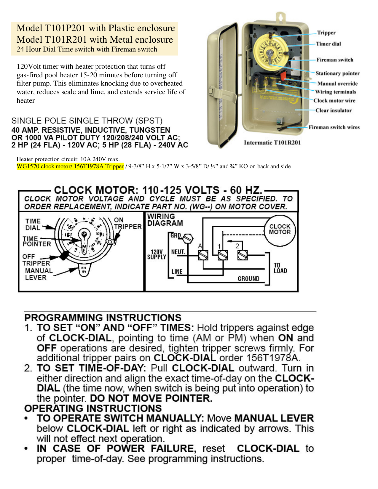
wiring diagram pressure plate terminal screw make sure wire insulation clears pressure plate minimum copper.How to wire T timerINTERMATIC T SUPPLEMENTARY MANUAL Pdf Download.