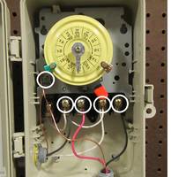
Wiring Instructions for an Intermatic Timer. Intermatic Incorporated manufactures timer switches designed for indoor and outdoor use.
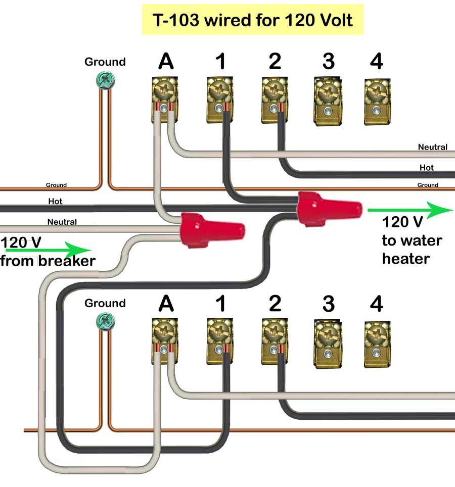
Many pool pump motors. WIRING INSTRUCTIONS: To wire switch follow diagram above.
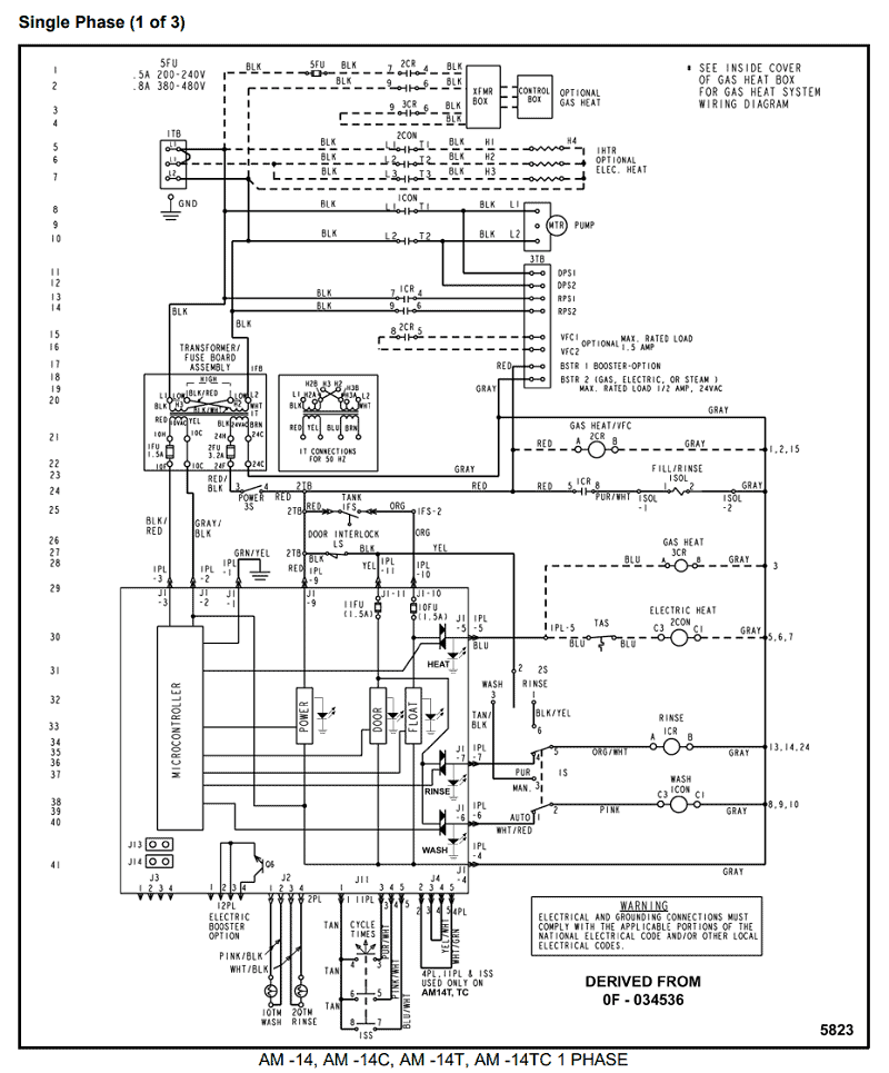
Use solid or stranded COPPER only wire with insulation to suit installation. See gauge selection.
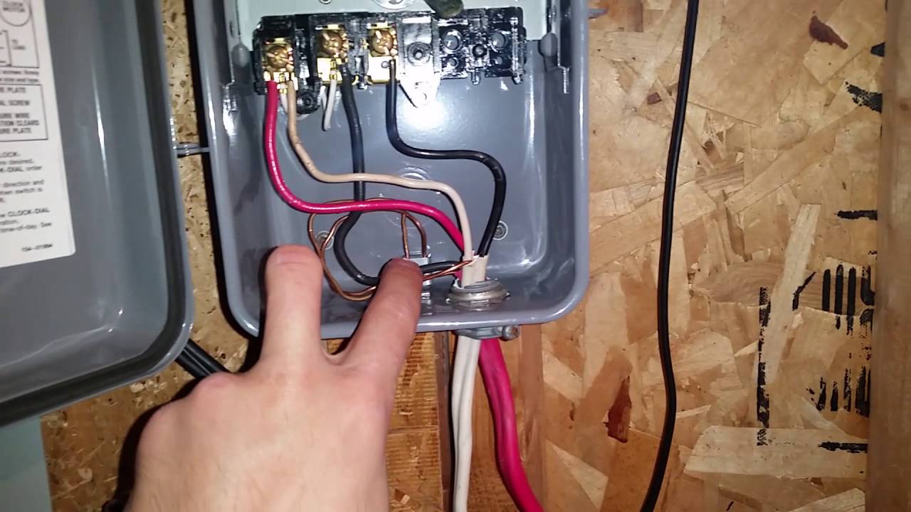
Highly versatile Heavy-Duty Timers are ideal for any application that requires a simple or complex ON/OFF schedule, regardless of load. No neutral connection.
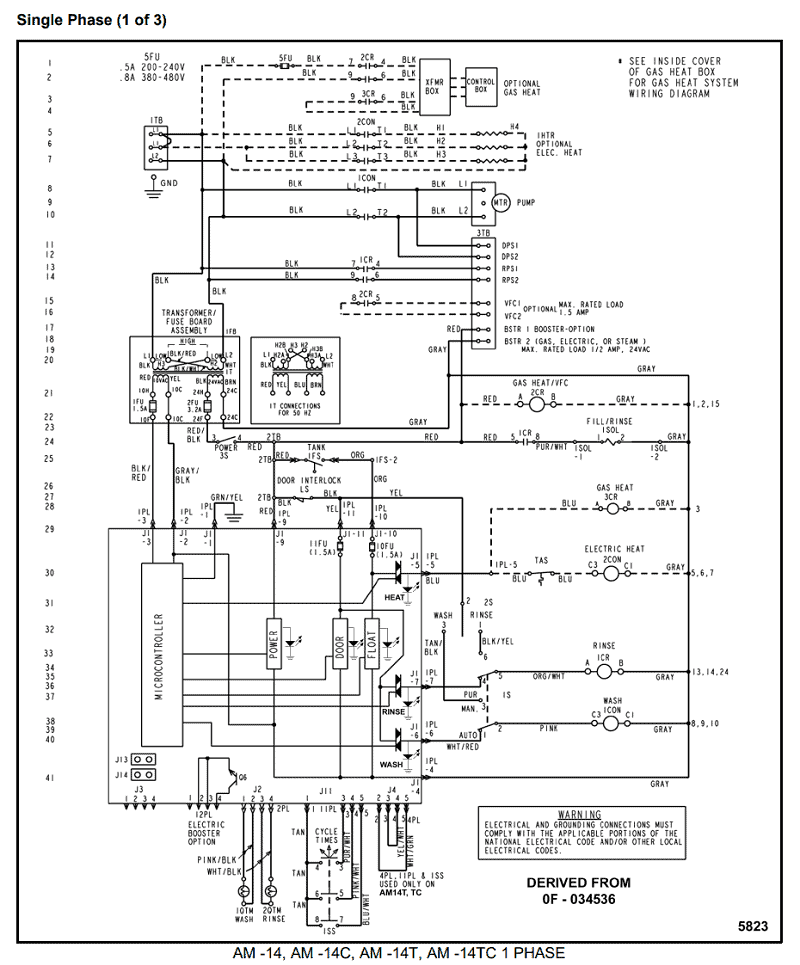
Installing an Intermatic T timer is a great way to dramatically reduce run time and energy costs. The following steps will provide a guide on how to install the.
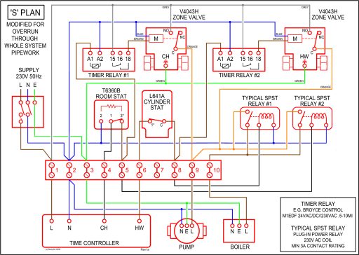
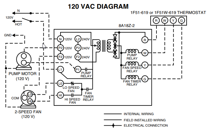
1) Diagram 1 showing how to change wiring: schematron.org controlV-Loadjpg. Move V clock motor.Intermatic Timer T Wiring Diagram Volt Wiring In conjunction with circuit design symbols, there are, in addition, a series of unique kinds of line designs to connect objects.
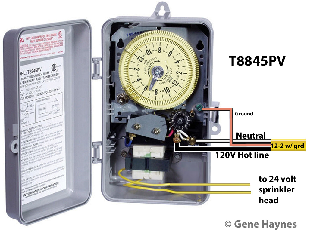
In case lines cross, utilize line jumps to show cable crossover. How To Install an Intermatic T Timer Connect the ground wire to the green screw located on the Intermatic timer mechanism. The ground wire will be green or exposed copper.
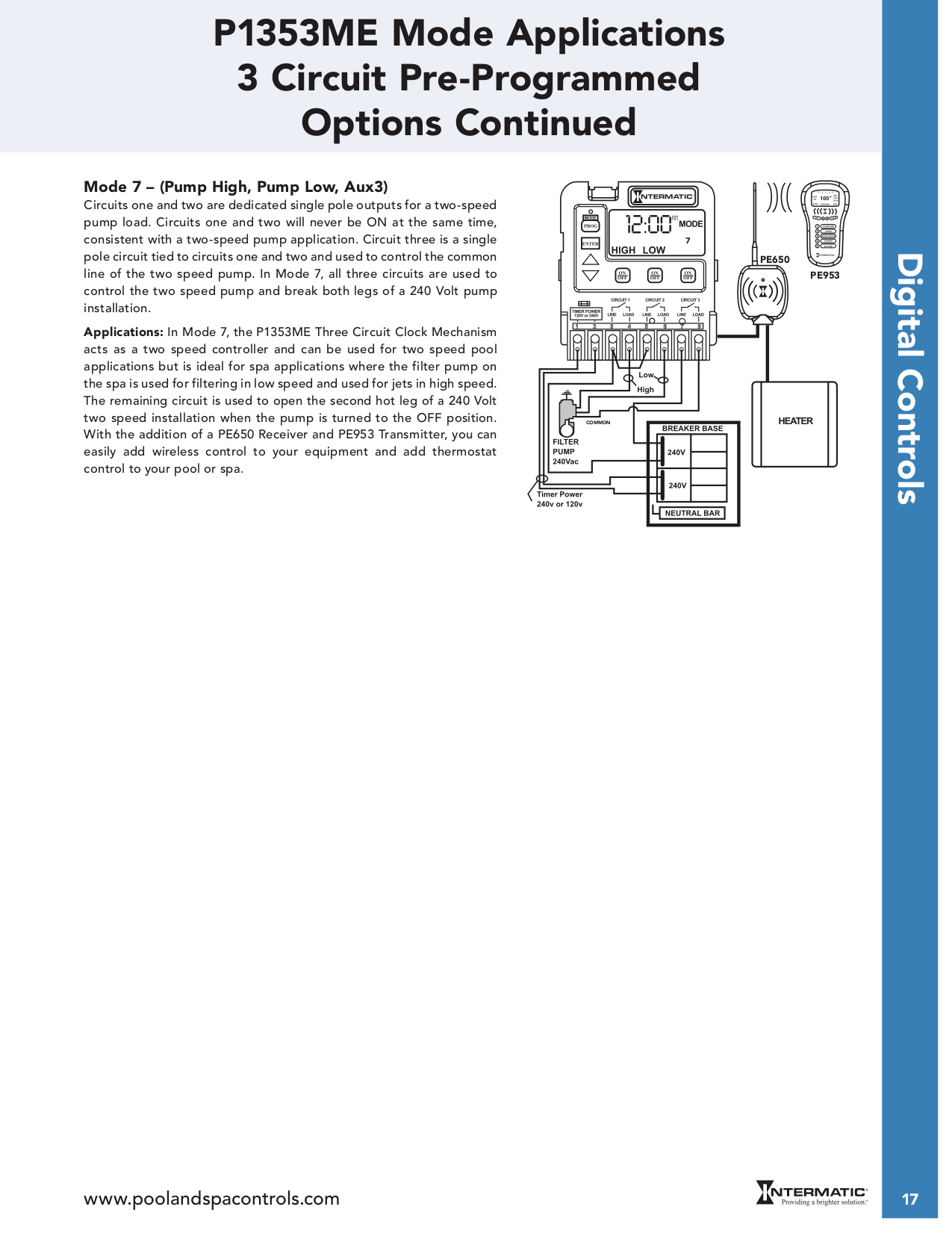
In the wiring diagram is says neutral.. when I connect it to the white neutral bar in the fuse box it trips the gfi same if I connect it to the ground bar.
Subscribe to Our Newsletter Sign-up for email alerts for products and software updates, new product releases and information about upcoming events. the intermatic ei series programmable electronic countdown in wall timer offers to the second accuracy in an auto off application easy installation and simple.
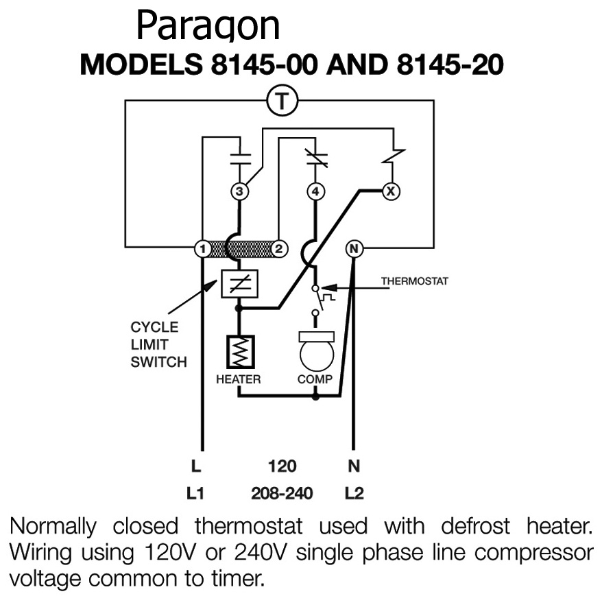
Jun 30, · Re: Intermatic Pool Timer Wiring jmpilon, I’m going to your thread for more views/activity. Rather than us try to make assumptions about your pump based on the pic of the wiring (which is a bit difficult to figure-out all wired so closely), we really should be going from the pump to the timer.How to wire WH40 water heater timer:Wiring Diagrams
