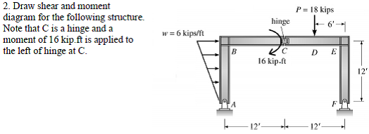
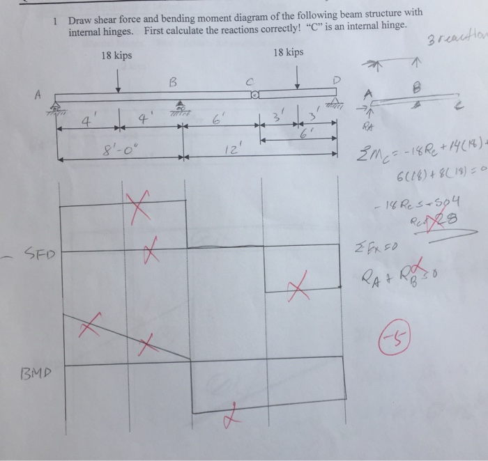
Shear and Bending-Moment Diagrams: Equation Form Example 1, page 1 of 6 .. Write the equilibrium equation for the sum of moments about the hinge.
ΣM. Solution to Problem | Relationship Between Load, Shear, and Moment. Problem The beam loaded as shown in Fig.
P consists of two segments joined by a frictionless hinge at which the bending moment is zero. internal hinge Load and moment diagrams for a given shear diagram · Moving Loads.
Bending Moment: It is an internal moment generated in the structure when an And at hinge joint we all know that, a beam/section is free to rotate. bending shear is zero) and this implies that no bending moment can be generated.
What will be the bending moment diagram for a simply supported beam. In the earlier Example, determine the internal system of forces at sections a-a Construct shear and bending-moment diagrams for the beam loaded with . Concept: A hinge can transfer axial force and shear force but not bending moment.
The internal bending moment at the hinge must be zero, but the And your teacher is right, no moment is transferred, but shear has been.Use this beam span calculator to determine the reactions at the supports, draw the shear and moment diagram for the beam and calculate the deflection of a steel or wood beam. Free online beam calculator for generating the reactions, calculating the deflection of a steel or wood beam, drawing the shear and moment diagrams for the beam.
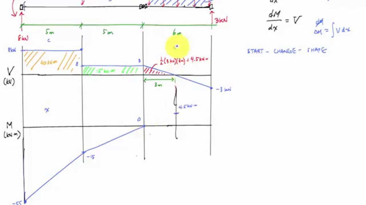
Internal hinges. Support locations.
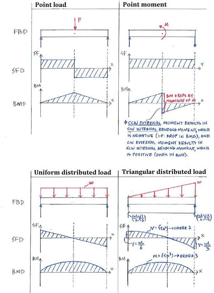
Points of zero shear (V = 0) — for moment diagrams only. Important features to remember when drawing the diagram: Concentrated forces cause an instant jump in shear. Concentrated moments cause an instant jump in moment.
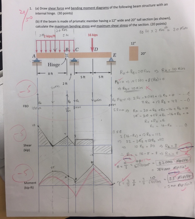
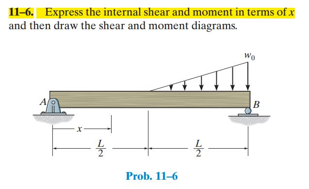
Order increases from load to shear to moment (that is, 1st order load diagram, 2nd order. Draw the shear and moment diagrams of the beam shown below.

There is a fixed support at point A, an internal hinge at point C, and a roller support at D. Show transcribed image text Draw the shear and moment diagrams of the beam shown below.
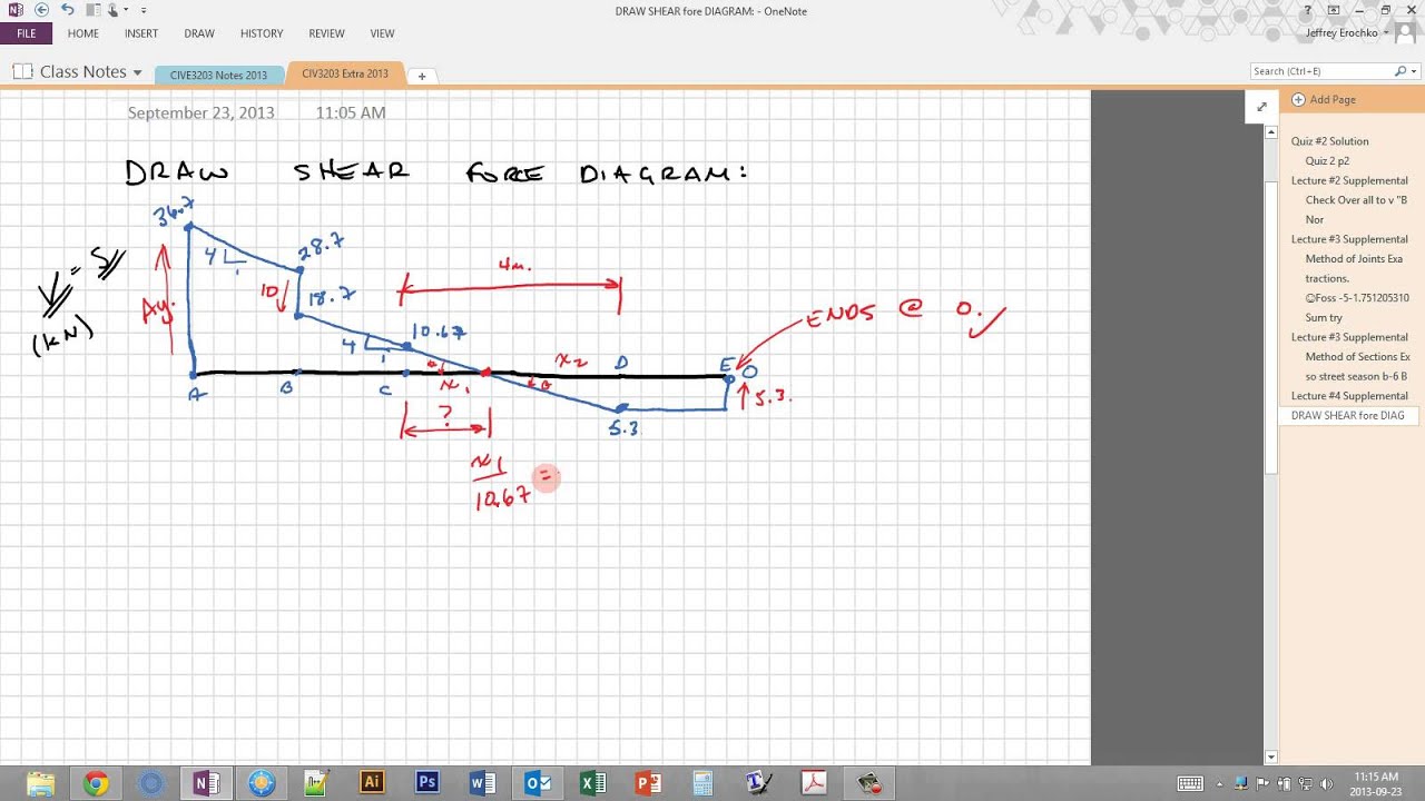
the bending moment in these members is zero BB’ = CC’ = ’A from Fig. (a) DD” = DD’ + A’A from Fig.
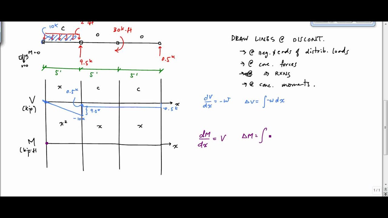
(a) 22 Note discontinuity in rotation at C – internal hinge location 23 Axial Force, Shear Force and Bending Moment Diagrams for Plane Frames Previous definitions developed for shear forces and bending moments are valid for both beam. Structural Axial, Shear and Bending Moments Positive Internal Forces Acting Shear and bending moment diagrams depict the variation of these quantities along the length of the member.
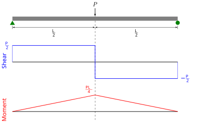
at C – internal hinge location. 23 Axial Force, Shear Force and Bending Moment.Shear Force and Bending Moment Diagrams – WikiversityFree Beam Calculator | Bending Moment, Shear Force and Deflection Calculator | SkyCiv
