Wiring.

2-Wire Relay Control Box. Model No.
Connect to. Furnace FEHA Series furnace, be sure to install the correct for all air conditioning units or heat pump units 2.
NORDYNE – manufacturer of Intertherm and Miller products- . Blower control box KSACCOMHA is used on Intertherm FEB electric Unplug motor connecter plug from receptacle on furnace wiring box by Plug 6- pin plug of 12 to 6-pin wiring harness to blower control box 6-pin receptacle. Connect condensing unit control relay or contactor to Y and C on blower terminal board.
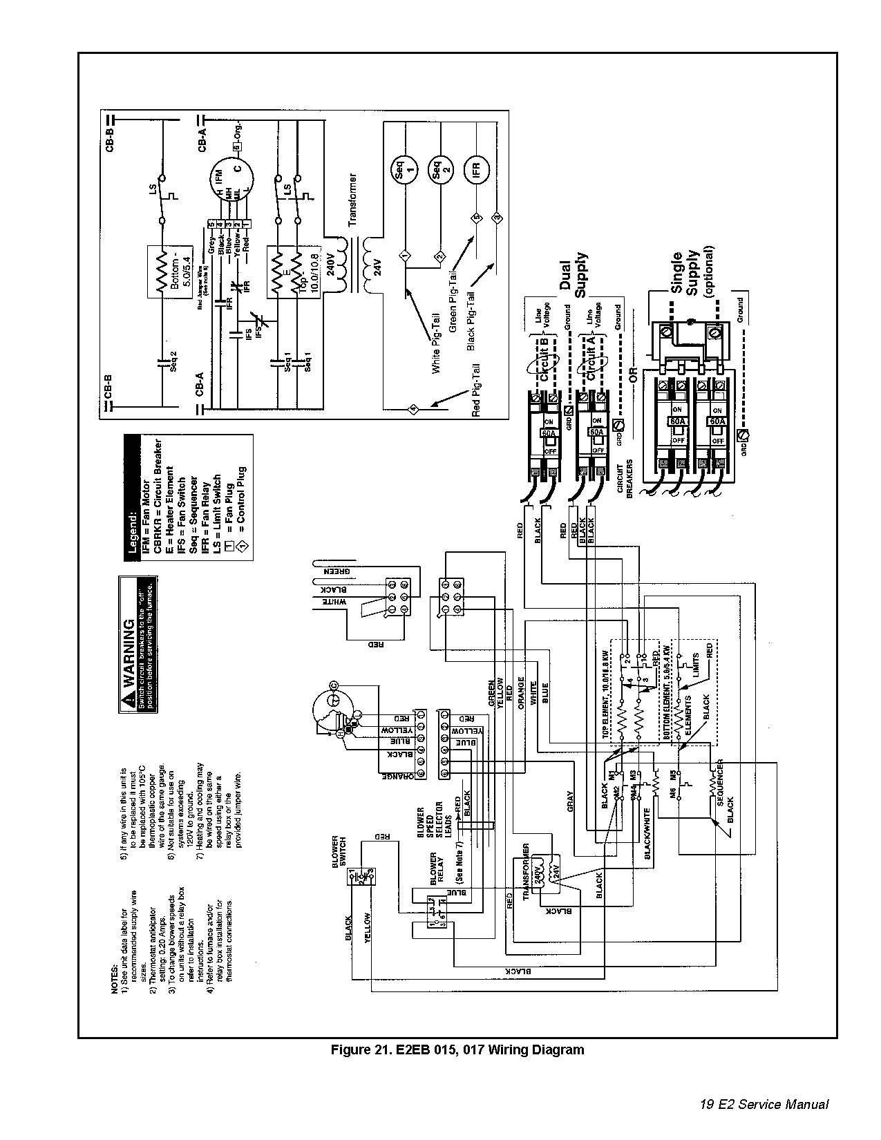
Heat Pump (4 to 7 wire) Relay Boxes install with current models of the E2 and current models of the E(1,2) NORDYNE electric furnaces respec- tively. The 2- wire. 2.
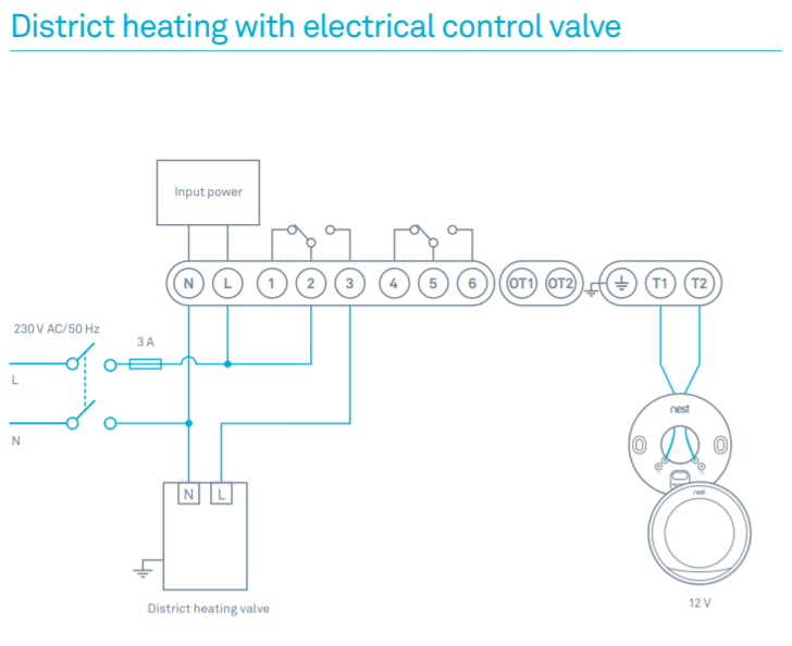
Figure 2. Cooling Blower.
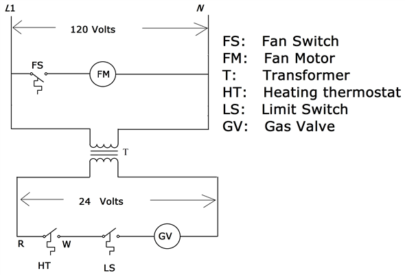
3. Install the upper relay mounting bracket to the blower and the lower relay mounting bracket to the furnace casing (see Figure 2). 6. Connect to 24 vac/40va/class 2 circuit.

See furnace/air handler instructions for control circuit and optional relay/transformer kits. 1. Couper le courant avant de.Heat Pump (4 to 7 wire) Relay Boxes install with current models of the E2 and current models of the E(1,2) NORDYNE electric furnaces respec-tively.
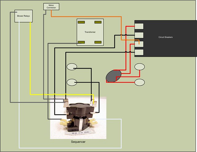
The 2-wire Relay Box has control switches switch (on the relay box) to HEAT, and the fan switch (on the relay box) to AUTO. Cooling: Set the furnace system switch to.
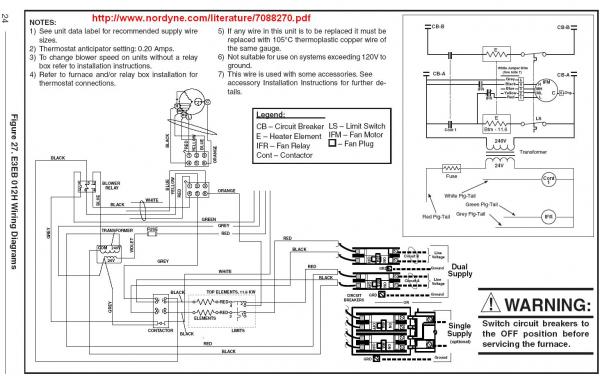
So I replaced the sequencers, limit switches, ac relay, transformer, and start capasitor, and installed a new digital non programmable t-stat. I wireed everything according to the wiring diagram for the furnace.
I have a few small problems. 1st. On the t-stat, the Auto/On switch for the fan when turned to On the blower comes on as.
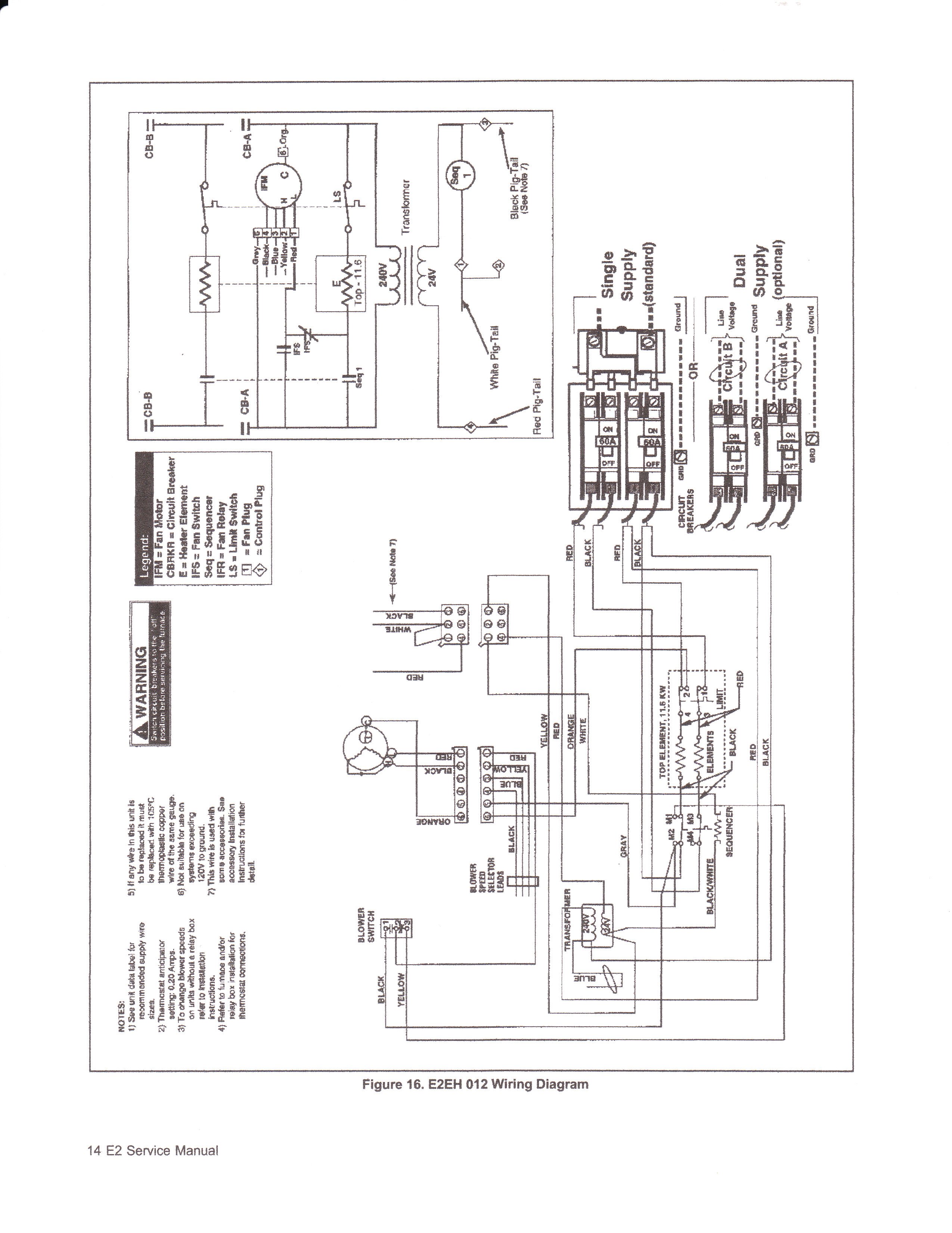
typical low voltage heat pump wiring blower low voltage connections red r w2 o c y r g o c y w2 yel wht grn outdoor unit a. blower is supplied with heating terminal #5 on the blower relay connected to med lo speed motor lead (red) and cooling terminal #2 to high speed motor lead .

88 91 EEC Wiring Diagram with Stater Relay and Neutral Gear Switch, 91 93 EEC Pinout Wiring Diagram with Control Module and Fuel Pump Relay, Constant Control Relay Module with Battery Junction Box and Powertrain Control, Engine Coolant Temperature with. Anticipator and Honeywell Thermostat Wiring Diagram for Heat Pump with System Switch, Changeover Relay and Honeywell Thermostat Wiring Diagram for Heat Pump with Compressor Contrator, Communication LED and Honeywell Thermostat Wiring Diagram for Heat Pump with Cool Relay.Intertherm Furnace Wiring Diagram Fan | Wiring LibraryNORDYNE E3 SERIES OWNER’S MANUAL AND INSTALLATION INSTRUCTIONS Pdf Download.
