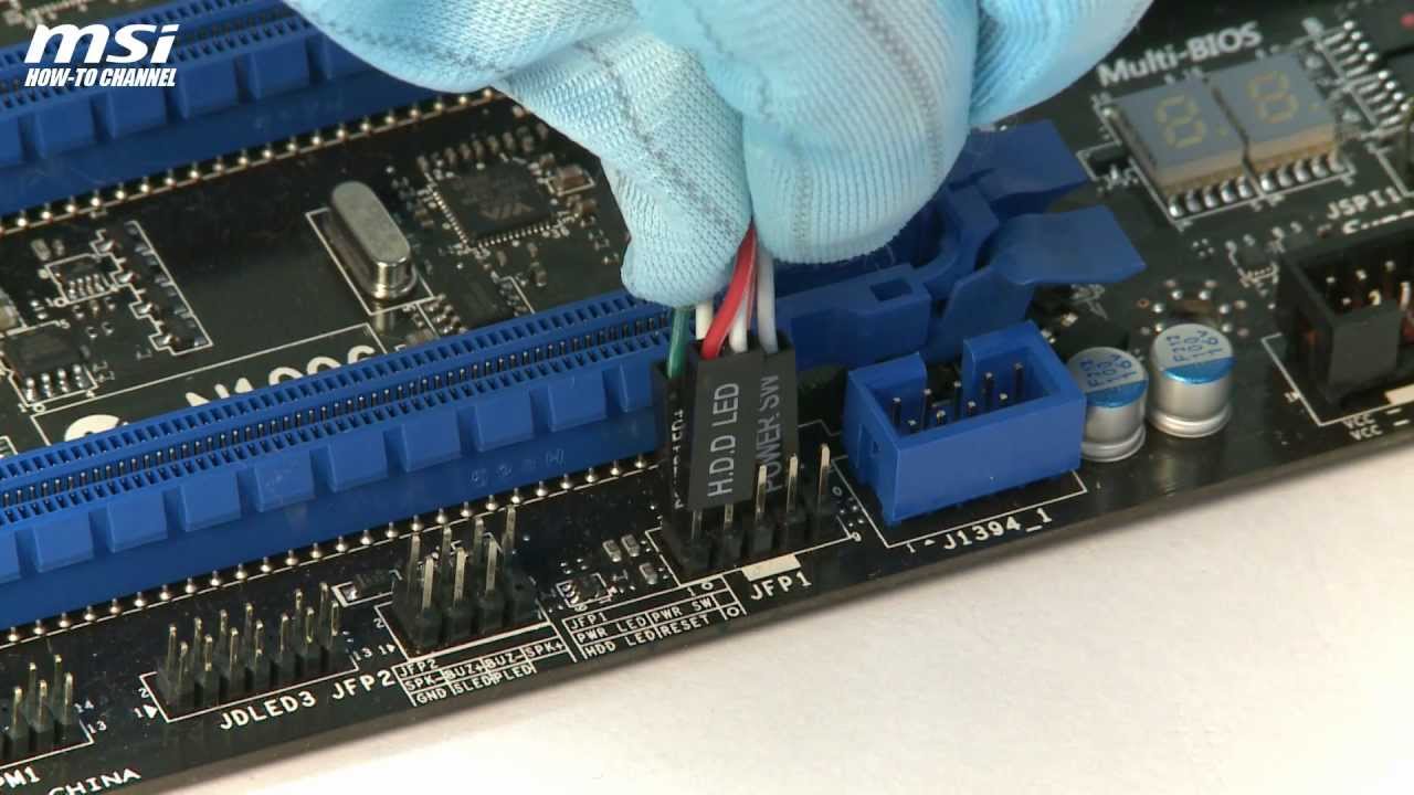
MSI MS Manual Online: Front Panel Connectors: Jfp1, Jfp2.
These connectors are for electrical connection to the front panel switches and LEDs. The JFP1.
On this motherboard, you’ll need to connect the cable to a pin header labeled JFP1. Consult the motherboard’s manual to determine the.
MSI B85M-G43 User Manual • English, Jfp1, jfp2: system panel connectors, Video Please use the diagrams above and the writing on the optional M-. Here is the diagram u can use.
I can’t wire the JFP1 with the computer case – cjpg. Jfp1, jfp2: system panel connectors, Jfp1, jfp2: system panel connectors , Jfp1, jfp2 – MSI Please use the diagrams above and the writing on the optional M-.View and Download MSI user manual online.
GAMING Series. Motherboard pdf manual download.
Also for: Ms Download Msi Motherboard PDF manuals. User manuals, Msi Motherboard Operating guides and Service manuals.
JFP1 AND JFP2 PINOUTS I NEED TO SEE A DIAGRAM SHOWING ME EXACTLY WHERE TO PLUG IN JFP1 AND JFP2 PINOUTS ON THE MSI – Computers & Internet question. Search Fixya. Browse Categories JFP1 is for the Power On switch, HarDDrive activity LED, Reset Switch, and a .

Dec 22, · The little blocks on the motherboard that are labeled JFP1 and JFP2 are where you plug in the loose case connectors/cables, which I was referring to earlier (Reset, Power Switch, etc.). MSI gm-p21(fx) MB, JFP1 AND JFP2 PINOUTS I NEED TO SEE A DIAGRAM SHOWING ME EXACTLY WHERE TO PLUG the cables on – MSI Computers & Internet question.MSI® HOW-TO Install front panel connectors (JFP1) – video dailymotionSupermicro Jfp1 Wiring Diagram – schematron.org
