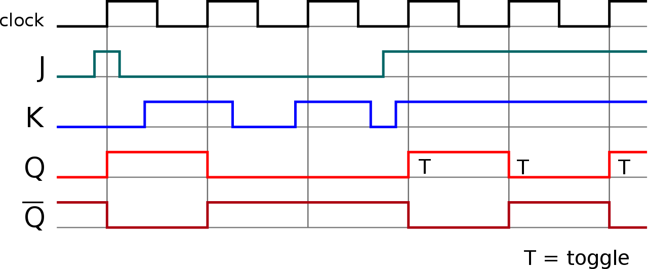
Figure 1 shows the Timing Diagram of a Positive-Edge-Triggered D Flip-flop and Table 1 is its Figure 1: Timing Diagram of the J-K Flip-flop Counter. The clock pulse [Clk] is given to the master J-K flip flop and it is sent through a NOT Gate and thus Master Slave J-K Flip Flop Timing Diagram.
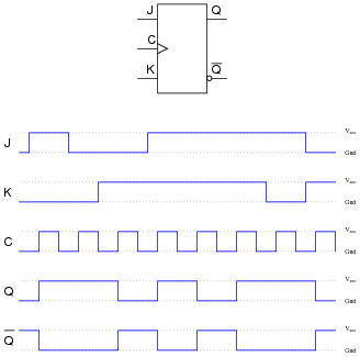
The JK flip-flop has two inputs, labeled J and K. J corresponds The timing diagram for the negatively triggered JK flip-flop. The standard symbol for the J-K FF is shown in view A of figure Figure – J-K flip-flop: A.
Standard symbol; B. Truth Table; C. Timing diagram.
JK flip-flop is a sequential bi-state single-bit memory device named after its as ( Table II) timing diagram for positive edge-triggered jk flip flop.Typical applications for SR Flip-flops. The basic building bock that makes computer memories possible, and is also used in many sequential logic circuits is the flip-flop or bi-stable circuit. Introduction – JK Flip-Flop.
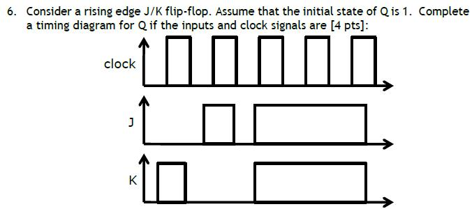
A JK flip-flop is a refinement of the SR flip-flop in that the indeterminate state of the SR type is defined in the JK type. Inputs J and K behave like inputs S and R to set and clear the flip-flop (note that in a JK flip-flop, the letter J is for set and the letter K is for clear). A Universal Programmable Flip-flop. The JK Flip-flop is also called a programmable flip-flop because, using its inputs, J, K, S and R, it can be made to mimic the action of any of the other flip-flop types.
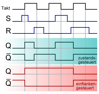
Fig. shows the basic configuration (without S and R inputs) for a JK flip-flop using only four NAND gates.
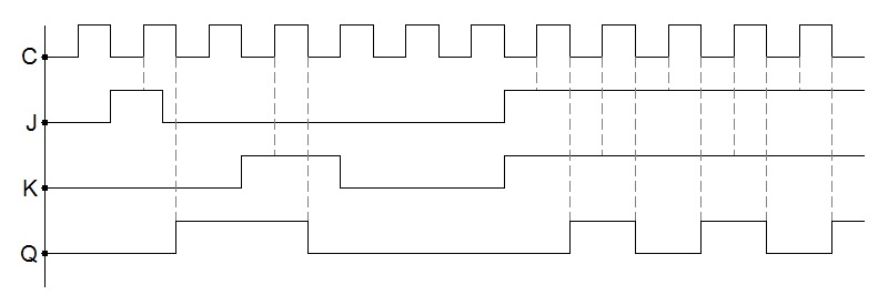
Ask students to identify those regions on the timing diagram where the flip-flop is being set, reset, and toggled. Question 17 Flip-flops often come equipped with asynchronous input lines as well as synchronous input lines.
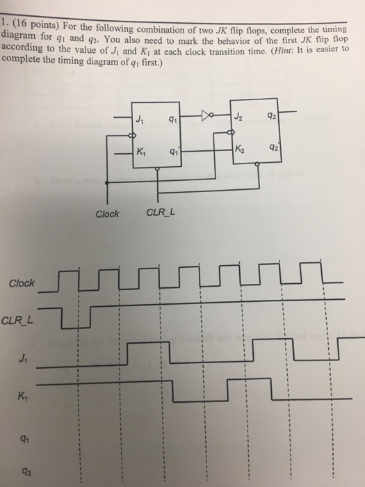
The TTL 74LS73 is a Dual JK flip-flop IC, which contains two individual JK type bistable’s within a single chip enabling single or master-slave toggle flip-flops to be made. Other JK flip flop IC’s include the 74LS Dual JK flip-flop with clear, the 74LS Dual positive-edge triggered JK flip flop and the 74LS Dual negative-edge.File:JK timing schematron.org – Wikimedia CommonsJK Flip Flop Diagram & Truth Tables Explained
