
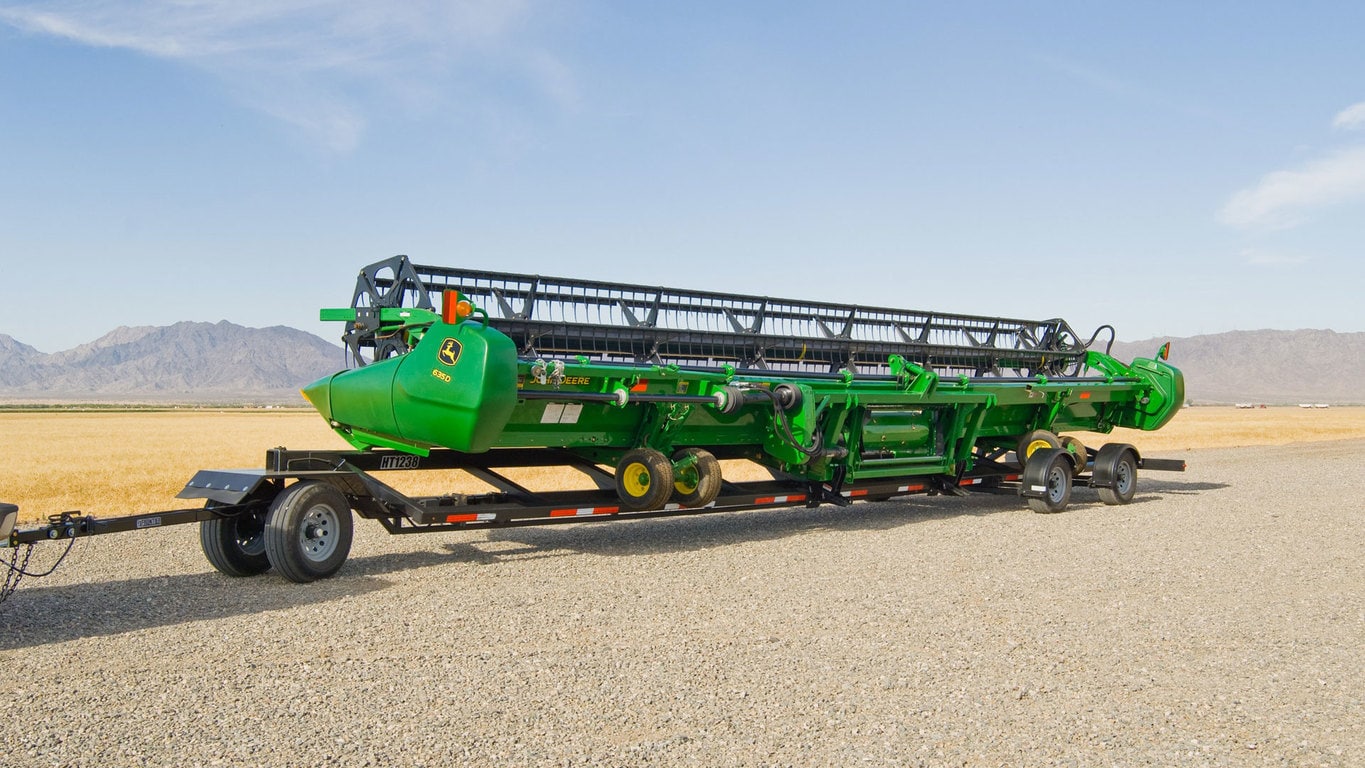
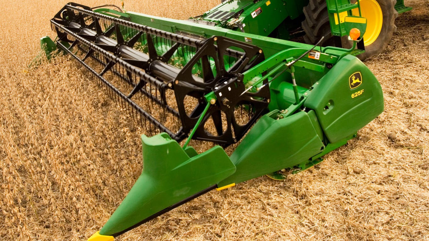
F HydraFlex™ Cutting Platform Headers from John Deere. Learn more Manual mode is for locking out the cutterbar in the rigid mode.
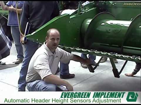
Float arms Field- installed header height sensors for flex platforms in the rigid position. Off-ground . Ground contacting height sensors for automatic height sensing when cutterbar is SE North Dakota, I put it on my f.
Not too hard. Have to replace the whole wiring harness on the header. Yeah the headsight was reccomended by my John Deere Dealer and they had it special order for me. All information, illustrations and specifications in this manual are based on the Skid Plates with Header Height Control Sensors – Rigid Platform Only (Optional).
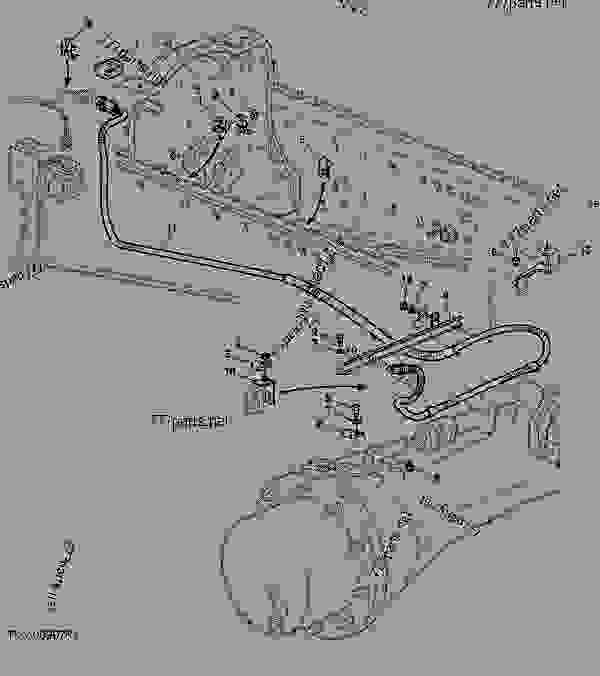
What pin # on the multiconnector harness is the wire? Our other F is currently waiting for a reel lift ram so I can’t lift the We have no power to any of the sensors on the other header now but power at the #20 combine. Discontinued – Header height sensors for F, F, F, F, and F Contains three sensor assemblies, main header wiring harness, and sensor.Aug 21, · PowerStrokeArmy > The Bunker > General Discussion Forum > Any John Deere Techs?
PDA. PM. Not receiving signal/return voltage from the Hydraflex hydraulic pressure sensor on an 05′ F header.

Sensor is working. What pin # on the multiconnector harness is the wire?
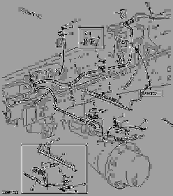
but if someone has access to the wiring diagram/schematics that. See your John Deere dealer.
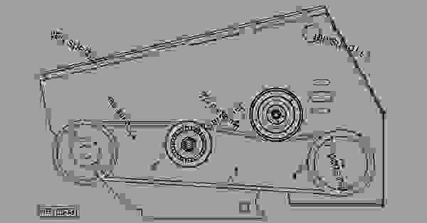
ER CONTOUR MASTER angle sensor voltage noisy or changing in an incorrect direction. 1: See your John Deere dealer. ER CONTOUR MASTER angle sensor voltage range less than VDC.
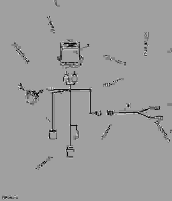
1: See your John Deere dealer. ER CONTOUR MASTER angle sensor “left” voltage range greater than VDC.
1: See your John Deere. with John Deere 70 Series STS and John Deere S-Series Combines.
• Refer to inside fold out portion of this guide for basic setup and Troubleshooting. • Refer to outside fold out portion of this guide for Calibration Procedures and a Sensor Voltage Map. IMPORTANT: This guide is .
Aug 21, · PowerStrokeArmy > The Bunker > General Discussion Forum > Any John Deere Techs? PDA.
PM. Not receiving signal/return voltage from the Hydraflex hydraulic pressure sensor on an 05′ F header.
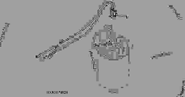
Sensor is working. What pin # on the multiconnector harness is the wire?
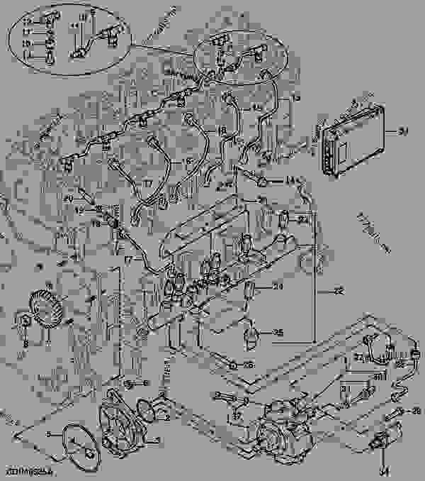
but if someone has access to the wiring diagram/schematics that. John Deere Electronic Solutions offers a range of custom-designed, specialty sensors that can survive the rigors of virtually any environment.
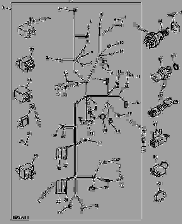
Utilizing state-of-the-art technology, we design electronic sensors that achieve an unprecedented level of accuracy and have proven themselves in multiple applications for various and diverse industries.Flex Header height sensors for rigid modeFlex Header height sensors for rigid mode