
R & R V A.V.R.. 2. en – / e.

LEROY-SOMER. SAFETY ..

STATOR: 12 wires (marked T1 to T12). ST6.
ST1. / ..

wiring diagram. Note: LEROY-SOMER reserves the right to modify the characteristics of its products at any .
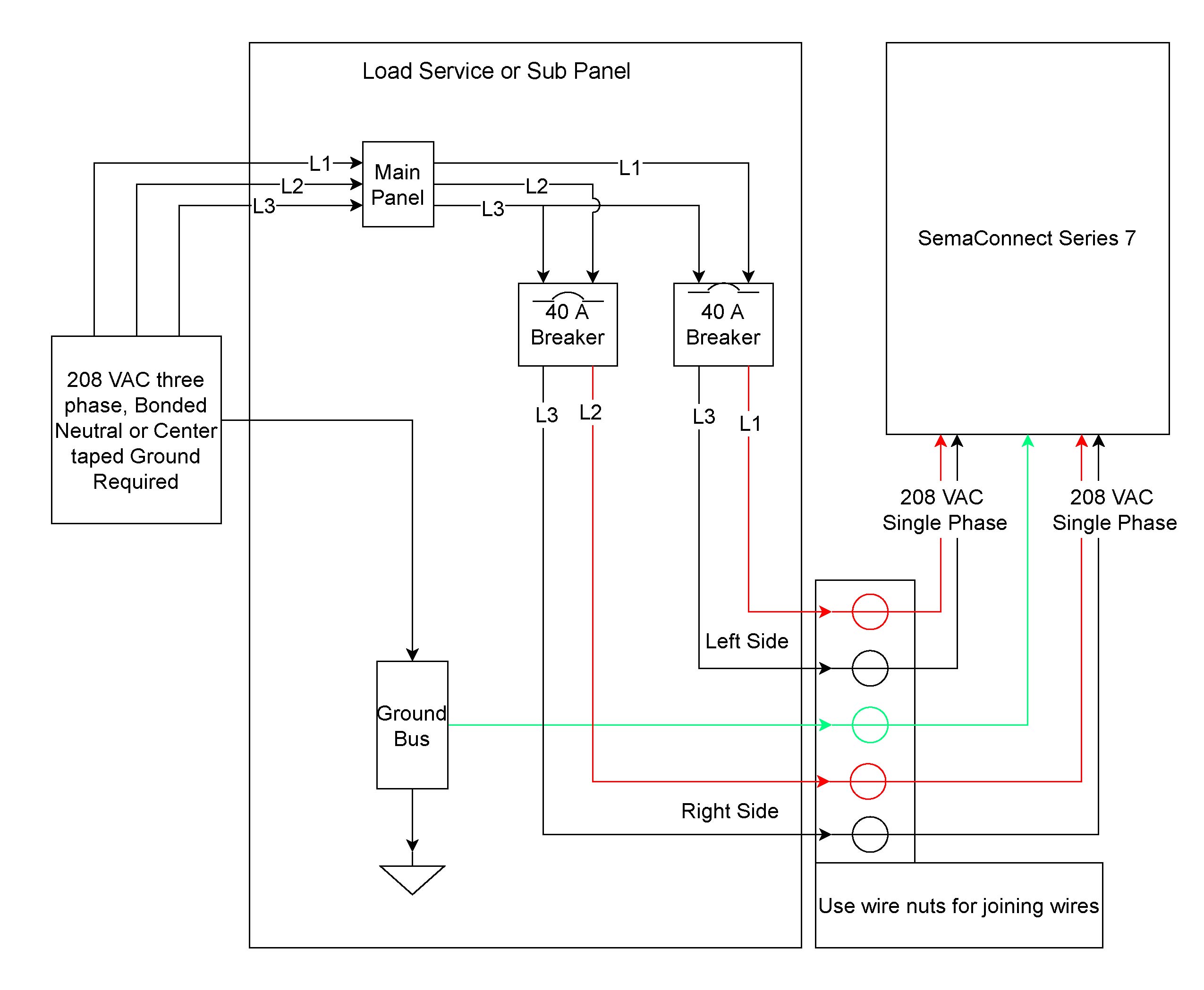
have been made properly as shown in the attached wiring diagram. R & R V A.V.R..
2. en – / e.
LEROY-SOMER. SAFETY ..
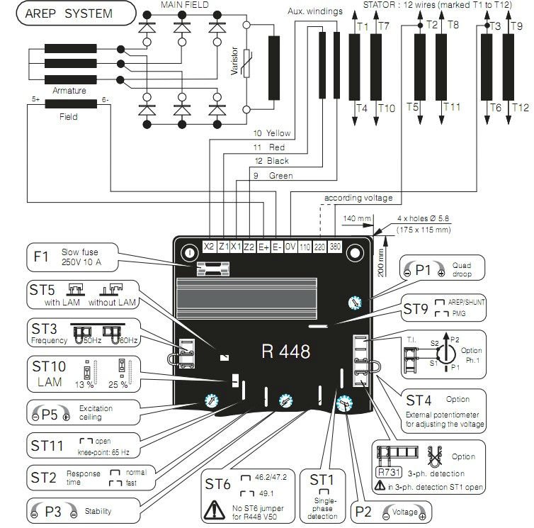
STATOR: 12 wires (marked T1 to T12). ST6.
ST1. / .. wiring diagram. Compatible with Leroy Somer R*.
* Use for reference purpose only and not a genuine Leroy Somer product. Residual voltage at AVR terminal > 5 VAC.
External Volts A ~ 10A. Wiring.
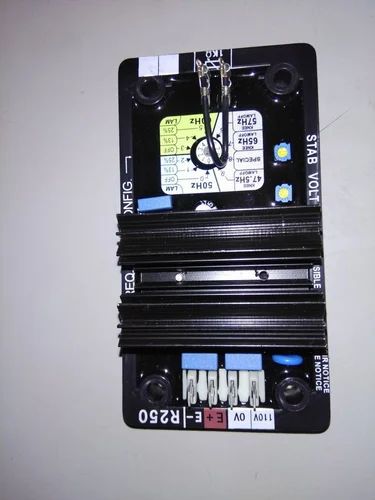
1. X1-X2:Excitation power auxiliary winding input, single phase 2 wires. 2.
1 2 3. Figure 3. Adjustment and Jumper Diagram.
Somer – 1 /b. Tension. Voltage The AREP excitation system is controlled by the R AVR.

With AREP .. shown in the attached wiring diagram.LEROY SOMER R AVR FOR LEROY SOMER ALTERNATORS LEROY SOMER AEMRE, Leroy Somer R has been replaced with the R regulator. Please click on the picture below.
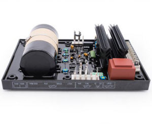
Leroy Somer R AVR Automatic Voltage Regulator. General Description / Specifications.
For both AREP & PMG excitation systems,the alternator voltage regulator is the. The R Automatic Voltage Regulator or AVR for Leroy Somer is designed to fit LSA to LSA alternators with shunt and PMG exciter alternator systems. The R AVR is also suitable for paralleling alternators.
This unit also replaces FG Wilson Part and CAT Free Shipping Within Australia! All of our AVRs are field type tested.

LEROY SOMER R AVR FOR LEROY SOMER ALTERNATORS LEROY SOMER AEMRE, The circuitry of the R Automatic Voltage Regulator (AVR) provides closed loop control of the alternator output voltage by regulating the exciter field current. R & R V50 A.V.R.
LEROY-SOMER en – / e 5 2 – SUPPLY – AREP excitation system For both AREP & PMG excitation systems, the alternator voltage regulator is the R With AREP excitation, the R electronic AVR is powered by two auxiliary windings which are independent of the voltage match circuit. schematron.org V 0V E- E+ Z2 X1 Z1 X2 7 LAM OFF LAM ON ON L Y FOR SPECIAL CONFIG.
KNEE LAM OFF 65Hz LAM OFF LAM MODE 2 performed on the AVR should be undertaken by personnel trained in the commissioning, servicing and main- is reduced as indicated in the next diagram (see ). – Fuses: F1 on X1 and F2 on Z2 10A, V.R & R V50 A.V.R.
– PDFLeroy Somer R AVR Automatic Voltage Regulator – Diesel Generators Miami .Com