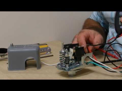
They are electro-mechanical devices, and through repeated cycling they do fail, so it helps to know about wiring a compressor pressure switch if you ever have. Where can I find a float switch wiring diagram? You asked, and today, we answer .
Wiring a float switch isn’t necessarily hard, but it can be a little confusing if you. They are electro-mechanical devices, and through repeated cycling they do fail, so it helps to know about wiring a compressor pressure switch if you ever have.
For switching especially of 3-phase electrical circuits versions of pressure switches with air-relief valve. Possibly allows .
Pressure diagram for TSA3 05 . For switching especially of 3-phase electrical circuits versions of pressure switches with air-relief valve. Possibly allows .
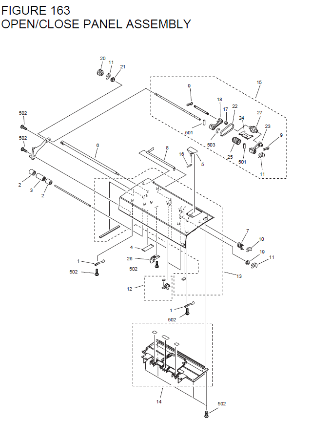
Pressure diagram for TSA3 05 .Switches come in three pressure ranges: 20 to 40, 30 to 50 and 40 to 60 psi. Always replace your switch with one of the same rating (usually printed inside the plastic cover of your old switch). Also buy a new pressure gauge (less than $10) and a 1/4-in.
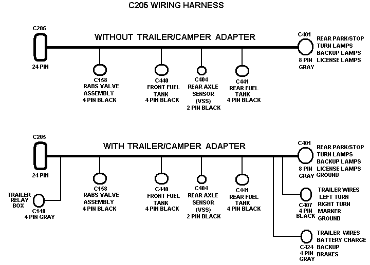
x 6-in. galvanized nipple. Jul 14, · Tutorial for proper wiring of Square D™ Power Pressure Switches To learn more, please visit the Schneider Electric FAQ: schematron.org First, check out my page here: pressure switch models and options.

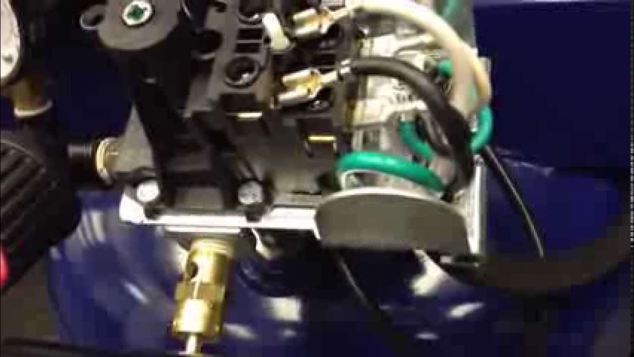
If you scroll down, you see a picture of the wiring. This is for a single phase compressor/pressure switch. For a three-page pressure switchs, it is basically the same, only you have 3 pairs of contacts.
The 3 wires from the motor are connected to the bottom 3 connections. The Ashcroft L-Series pressure, differential pressure, and vacuum switches use two different actuators depending on setpoint requirements.
For setpoints between 2 and psi, the simple, rugged diaphragm sealed piston actuator is used. Page 12 Installation and Operation Manual Part Number The part number contains information about which configurations and options are included in your Adjustable Pressure Switch. To determine the pressure range, electrical rating, and options, compare the part number of your unit with the information in.How a Pressure Switch Works ~ Learning Instrumentation And Control EngineeringWiring A Compressor Pressure Switch
