Find garage door opener support materials from Chamberlain Group.
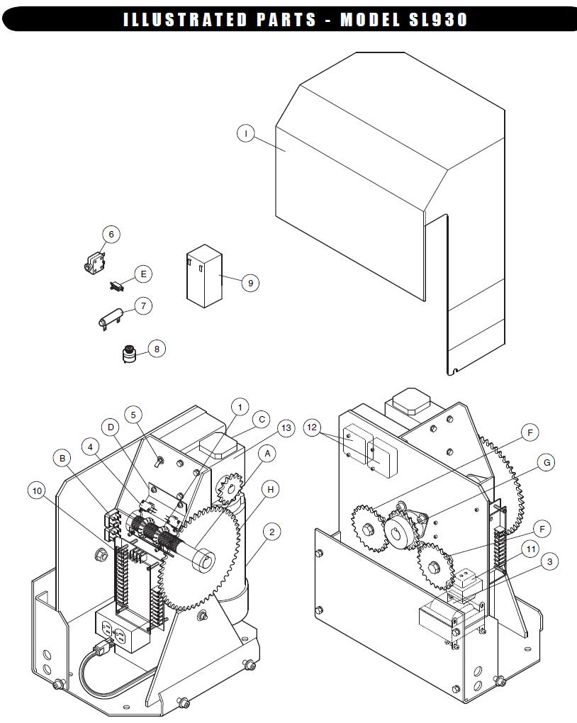
Whether you have Chamberlain or LiftMaster products, you’ll find the resources you need. This page displays Liftmaster Compatible Garage Door Opener control motor boards repair parts, Liftmaster Compatible “Recommended Surge Protection when replacing safety sensors or circuit boards” , 41A, 41A push button wiring. The following chart outlines adjustment procedures.
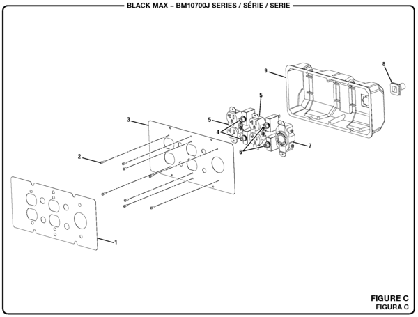
. 41A Receiver logic board assy. 2 light operator.
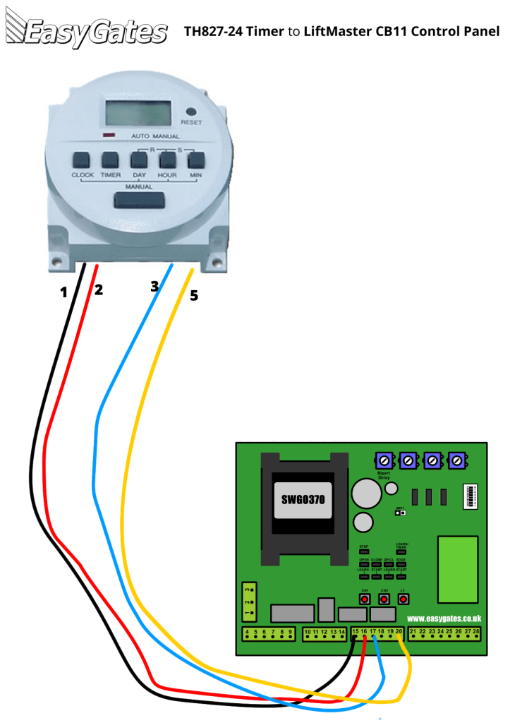
41A Receiver logic . LiftMaster chart below. LiftMaster boards are fully compatible with Chamberlain models.
Call us to be sure if you have a Sears Craftsman model. Please contact. Fasten the manual near the garage door after installation.
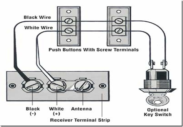
□ The door If you have a one-piece door, the installation of your garage door . Diagnostic Chart.I need a wiring diagram for a Liftmaster R GARAGE DOOR OPENER – Sears Craftsman LiftMaster question.
I need a wiring diagram for a Liftmaster R GARAGE DOOR OPENER. Posted by Anonymous on Jul 22, I need a wiring diagram for a Chamberlain Liftmaster LM Garage Door Opener.
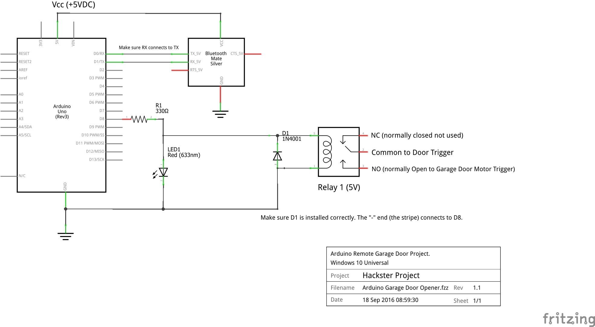
One that shows where all the wires inside hook up. Wiring diagram for garage door opener.
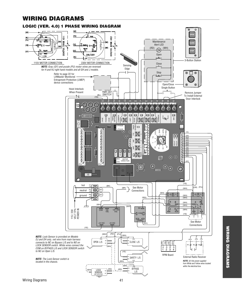
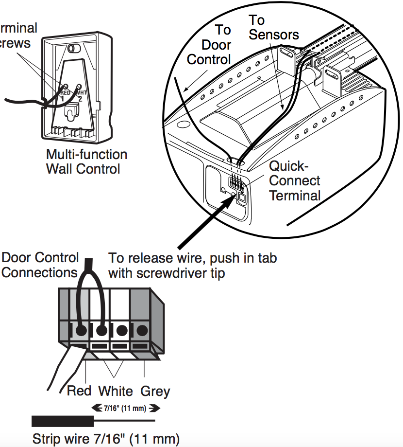
The sensor for the garage door opener was accidently knocked off. How do I fix it – there are 3 wires and only 2 places to wire it too. I need a wiring diagram to hook up the wires on my garaged door opener. Craftsman LiftMaster Chamberlain Garage Door Opener Wireless Keypad Model LM Security+.
Consult your manufacturer’s control connection diagram for instructions on connecting two or more 3-button control devices. Figure 1.
• Use a screwdriver to pry open the receiver cover. NOTE: The slide switch is factory set to the N.C.
position (otherwise the opener will not operate). Verify this setting. Download Chamberlain Garage Door Opener PDF manuals.
User manuals, Chamberlain Garage door opener Operating guides and Service manuals. H, J, AND HJ T AND APT GH A L E R T S Y S T E M M A I N T E N A N C E PATENT PENDING The Maintenance Alert System™ allows the installer to set an internal Maintenance Cycle Counter.
The Logic 4 operator incorporates a self-diagnostic feature built into the (MAS) Maintenance Alert System LED. An LED on the 3-button station will.How do i wire safety sensors to my 41a model liftmaster – FixyaSOLVED: Wiring diagram for garage door opener – Fixya
