CDO Commercial Protector System®.
OWNER’S MANUAL. Model CPS-LR.
Install the Protector System®. When properly connected and aligned, the sensor will.
LiftMaster CPS-UN4 and CPS-RPEN4 photo sensors or a monitored 4-wire sensing edge (via a CPS-EI Edge Interface Card) are optional. CPS® Commercial Protector System® J industrial-duty jackshaft door opener ( installation manual). INSTALLATION INSTRUCTIONS.
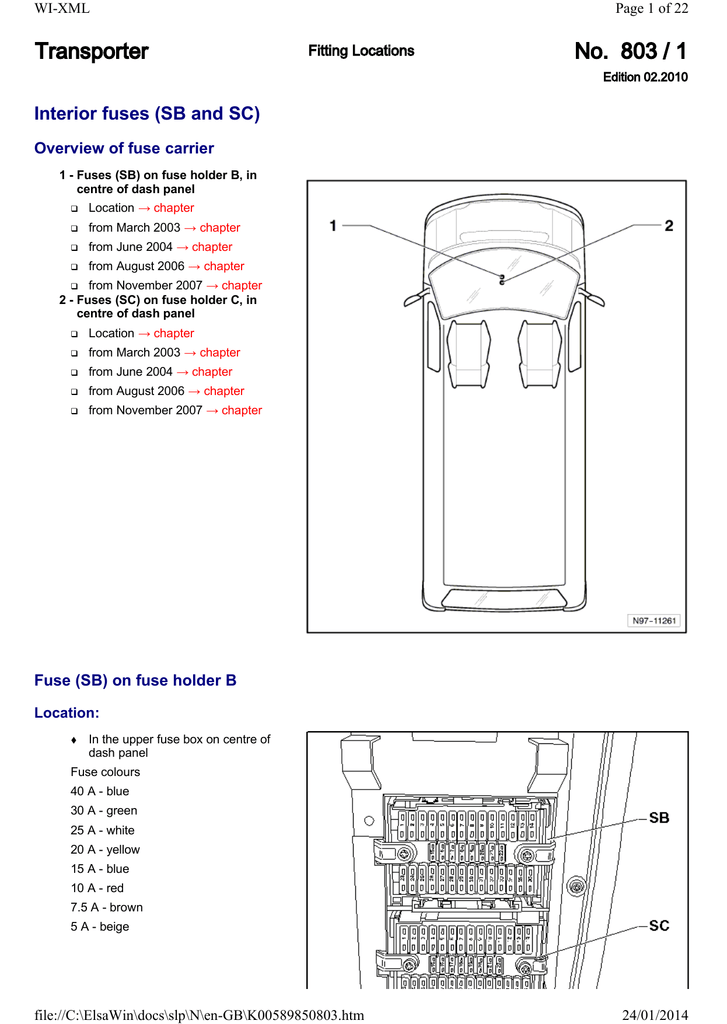
To reduce READ AND FOLLOW ALL INSTRUCTIONS. The Commercial Protector System® (CPS) is suitable for LiftMaster.
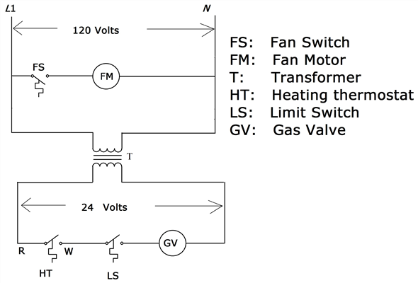
CPS-EI – LiftMaster Commercial Protector System Edge Interface Installation Manual. Download Manual.
Feedback. Was this information helpful? Yes No.
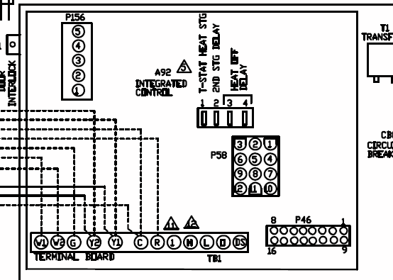
COMMERCIAL PROTECTOR SYSTEM®. CPS3 Installation Manual.
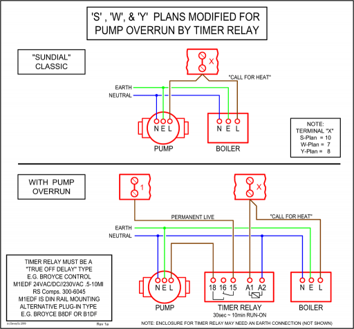
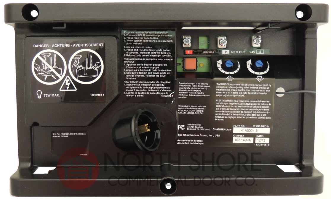
To prevent SERIOUS LiftMaster Monitored Entrapment Protection devices are for use with .51 Pass-point not detected (Arm 1) Check yellow pass-point wiring. If limits are not If limits are not 52 Pass-point not detected (Arm 2) accurate, reprogram. ON/OFF SWITCH POWER WIRING NOTE: Before running power wiring refer to wiring specifications on page 15 for correct wire gauges.
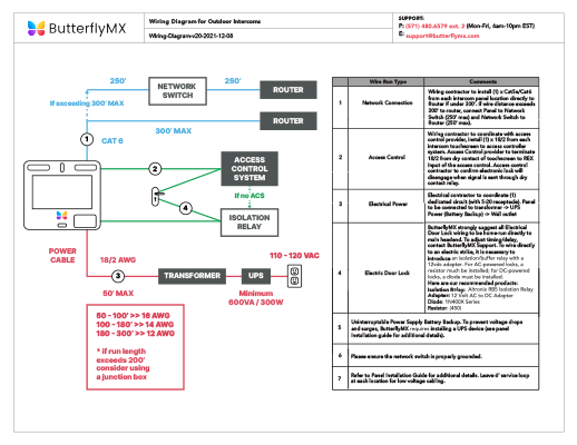
Secure all electrical power connections inside the disconnect switch electrical box. Refer to electrical wiring diagrams on pages IMPORTANT: On three phase operators, power connections must be properly phased. GARAGE DOOR OPENER ASSEMBLY/INSTALLATION MANUAL Test the Protector System Without a properly working safety reversal system, persons (particularly small children) could be SERIOUSLY INJURED or KILLED by a closing garage door.
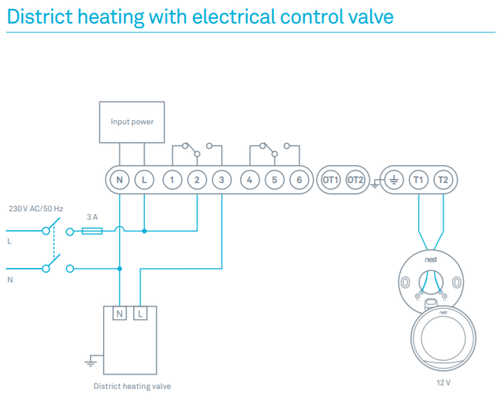
• The gap between the bottom of the garage door and the floor. Otherwise, the safety reverse system may not work properly.
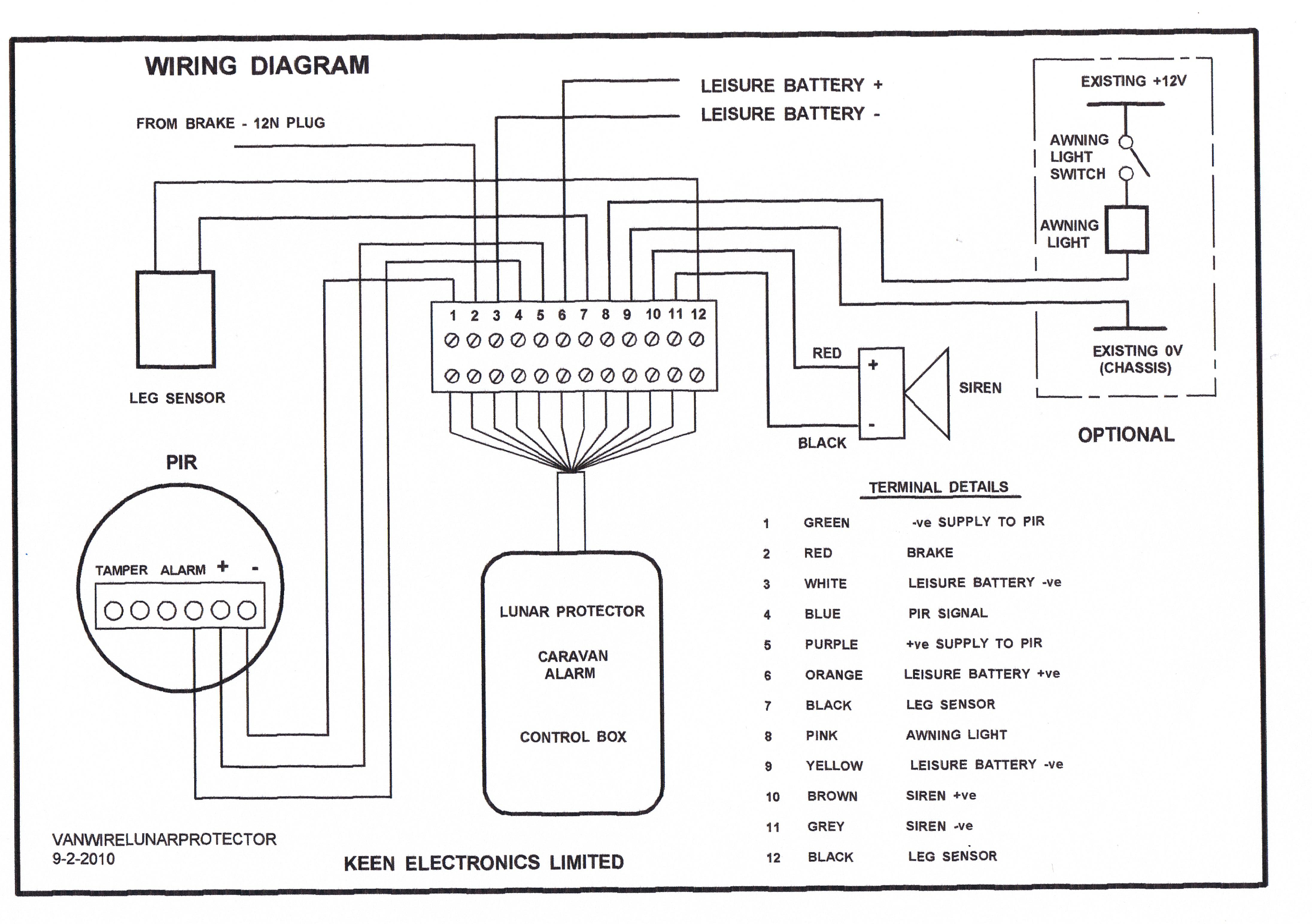
See page The f loor or t he door should be repaired. ONE-PIECE Door Installation Y ou may find it helpful to refer back to this page as you proceed with the installation of your opener. Access Door Floor must be level across width of door Safety Reversing Sensor The Chamberlain Group, Inc.
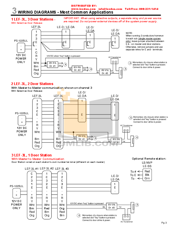
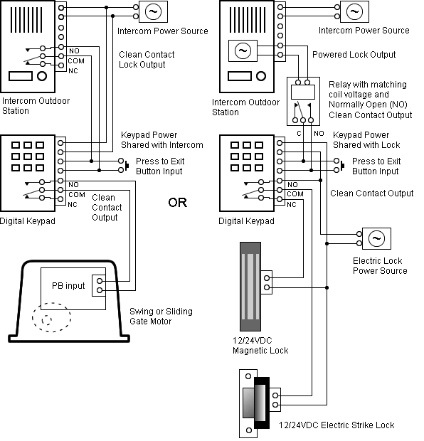
WIRING DIAGRAM & INSTRUCTIONS Model: DH, DJ and DH/J APPLICATION REQUIREMENTS This wiring modifi cation is available to models DJ and DH/J Standard-Duty operators with 24Vac control circuits and “D1” type wiring.Liftmaster Commercial Protector System Saftey Eyes MODEL CPSCHAMBERLAIN LIFTMASTER PROFESSIONAL SW USER MANUAL Pdf Download.