Locknetics offers many sizes of each. Herculite door brack- connections (see wiring instructions on next page).
Install circuit board(s) (if OUTSWINGING MAGNETIC LOCK with AVS SEE DIAGRAMS ABOVE. PC BOARD.
jurisdiction. Locknetics manufactures fire rated mechanical latching devices.
ers the mechanical installation, wiring, and manual programming aspects of the locks. The magnetic lock uses significantly less current so more locks can be loaded onto a power supply.
.. (See chart on page 20 “Table of Outputs”.) LED. Wiring should be protected by conduit. Wire leads provided Other sex nuts, of different lengths, are available from Locknetics distributors.
Refer to the last page Slide the TJ mounting plate onto the magnetic lock assem- bly. Center it and.
LOCKNETICS. M I MN MORTISED MAGNETIC LOCK. INSTALLATION AND WIRING INSTRUCTIONS.
Birch Street, Forestville, CT. LOCKNETICS. M I MN MORTISED MAGNETIC LOCK. INSTALLATION AND WIRING INSTRUCTIONS.

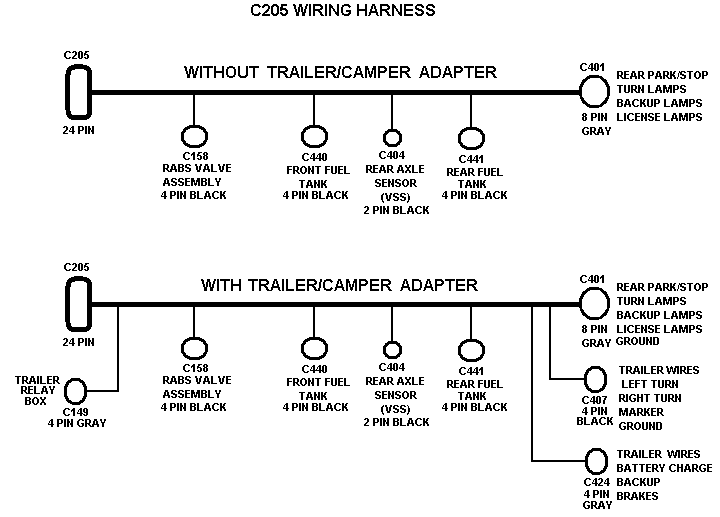
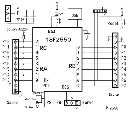
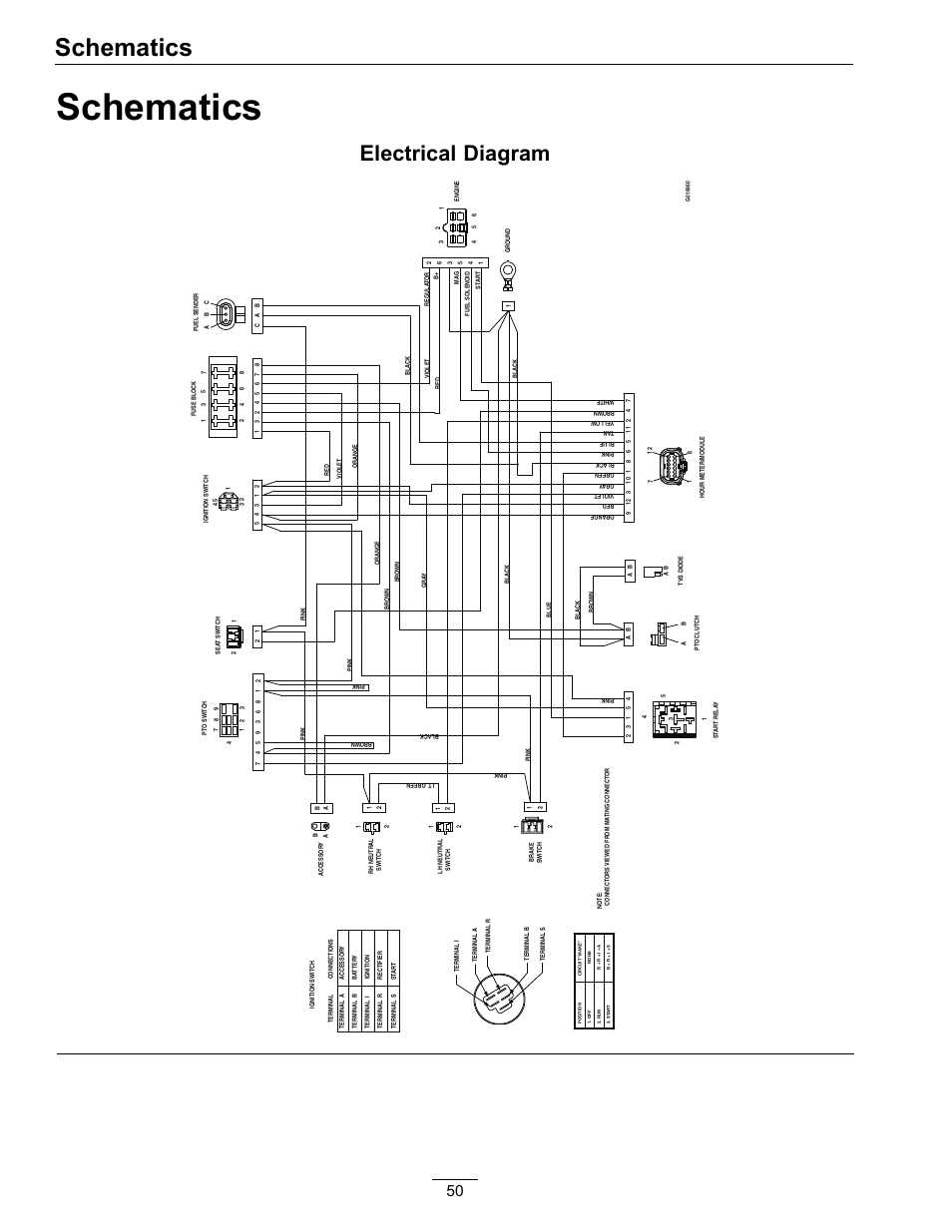
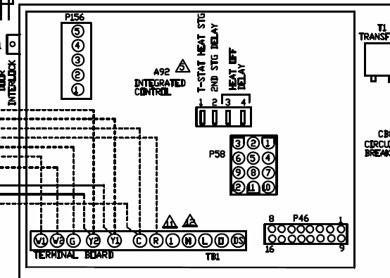
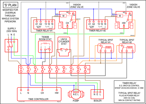
Birch Street, Forestville, CT.- WIRING INSTRUCTIONS— magnetic lock or fail safe strike with button, keypad and PIR wired in series Power Supply for fail safe strikes and magnetic locks should be DC. If this is not available you may use an AC power source and wire inline a “Full Wave Bridge” rectifier. This will conver t the AC to DC.
M Series Electromagnetic Lock. The M Series offers 16 models that are designed to make quick, light work of installation with a bayonet mounting bracket and slide-together components for easy in-field handing and wiring.
Pass control/monitoring wiring through wire access hole in frame and through wire hole in mounting bracket. Mount bracket using pan head screws and flat washers.
Do not completely tighten screws – it will be necessary to adjust the position of the bracket in step 5. OUTSWINGING MAGNETIC LOCK with AVS INSTALLATION INSTRUCTIONS.
Systems from 1 to doors Free system design. Call us todayShop Online Now · BBB A+ RatingTypes: Hotel Systems, Access Control Systems, Magnetic Locks.
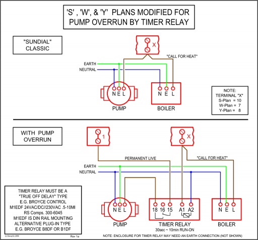
A: The G in the Locknetics G stands for “Gate” and is a specific Gate type variant of the Locknetics and differs from the in that the G+ Gate Lock is a weather resistant electromagnetic lock with lbs. of holding force. It is designed for use on all types of sliding and swinging gates.Remote Control Transmitter & Receiver Set (Great For Access Control)Locknetics Maglock Wiring Diagram Collection | Wiring Collection
