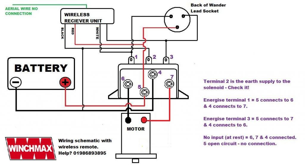
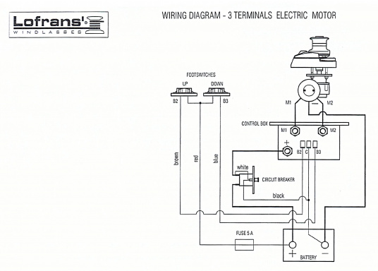
WIRING DIAGRAM – 2 TERMINALS ELECTRIC MOTOR. CONTROL BOX CODE: – LOfrans’.
W IN D L A S s Es. WIRING DIAGRAM CODE.
MANUAL DE INSTRUCCIÓN. Pg. Pg .
This Lofrans circuit breaker protects the power line from short circuit and the windlass motor in case of overheating. It must Use 6 mm faston to connect these wires to the terminals of the Control Box. 6.
Lofrans Windlass (3 terminals motor). For other makes and models of equipment please refer to the manufacturer’s wiring diagram. CONTROL BOX AND.
The Control Box is an electric unit made up of two remote control switches enclosed inside a special container which protects it from marine corrosion. The entire. WIRING DIAGRAM – 2 TERMINALS ELECTRIC MOTOR. CONTROL BOX CODE: – LOfrans’. W IN D L A S s Es.
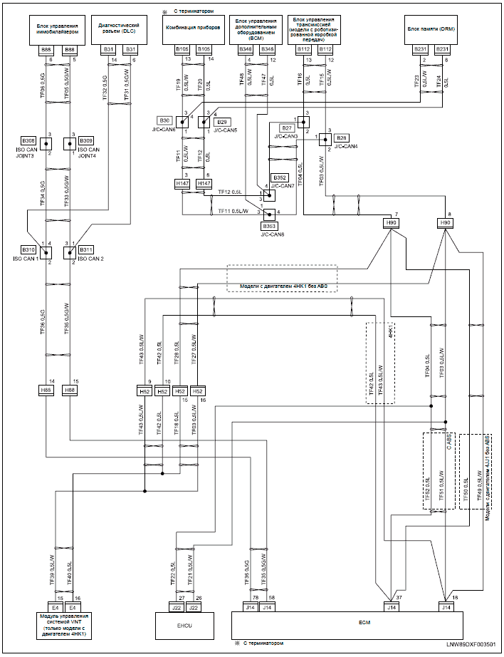
WIRING DIAGRAM CODE.Nov 17, · Jamestown Distributors TV: Retro-Fitting A Lewmar Windlass: Wiring the Control Box. Power and Motoryacht Magazine’s Ken Kreisler and Lewmar’s Tom Fleming provide A . the wiring diagram shows.
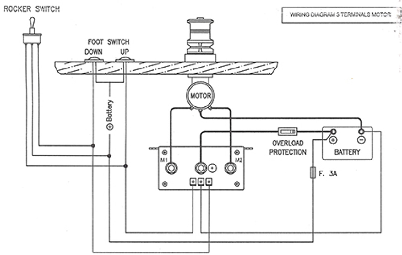
Introduce the chain into the gipsy, operate the “UP” switch of the foot switch or remote control and the chain will automatically be fed into your locker. Take care to keep hands and feet well clear of incoming chain. If the windlass runs in wrong direction, change over M1 and M2 cables at the control box.
With % stainless steel housing and a sleek flush-mount design that hides the motor down below, the V is one of the most attractive and durable windlasses on the market. 2. The Control Box is the solenoids box.
Please read carefully the Control Box instructions. 3. This size must be increased of 30% when the length of the positive plus the negative cables are more than 10 mts.
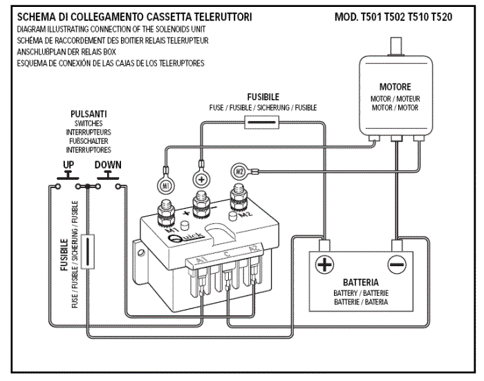
4. This Lofrans circuit breaker protects the power line from short circuit and the windlass motor in . Download Lofrans’ installation manuals, user’s manuals, technical specifications, instructions, 3D CAD models and deck templates.LOFRANS Relay Box for Windlass / 3-pole from 54,95 € buy now | SVB Yacht and boat equipmentHow to Fix Your Electric Windlass 9 out of 10 Times – Sailfeed
