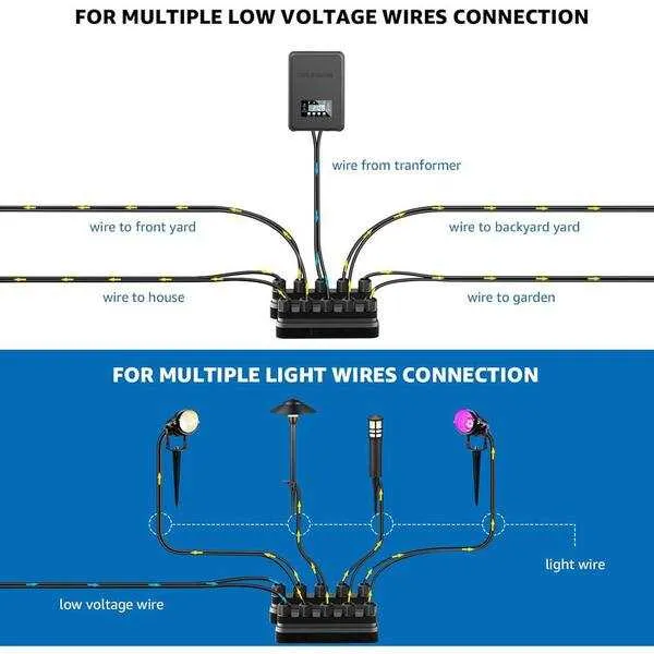
Install a 12 V toroidal transformer rated at least 30 % above the combined wattage of all fixtures; this reserve eliminates dimming on runs longer than 25 m and leaves capacity for future additions.
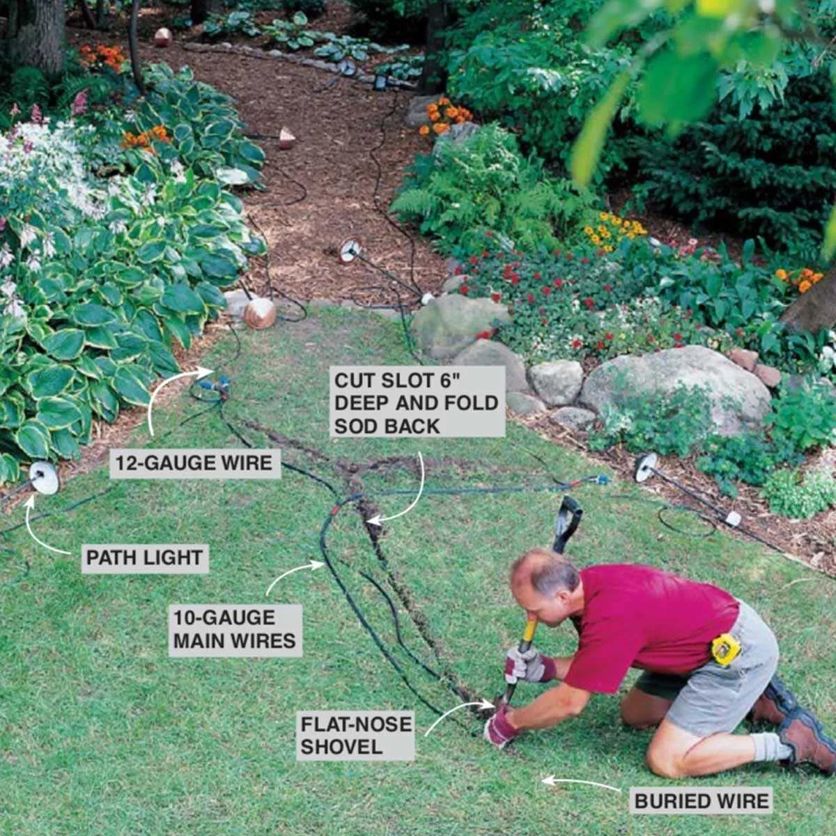
Route 14-gauge direct-bury twin-lead no deeper than 15 cm, maintaining a straight main line. Before adding T-connectors, calculate drop: keep <3 % loss by limiting each spur to 60 W and 10 m length.
At every lamp, use crimped heat-shrink butt joints filled with dielectric grease instead of twist connectors to block moisture. Verify the circuit with a multimeter–expect 11.5 V at the farthest fixture and adjust the transformer’s tap if the reading falls below 10.8 V.
12-V Landscape Illumination Schematic

Select a 120-to-12-V magnetic or electronic transformer rated at least 25 % above total lamp wattage; this headroom keeps the secondary winding cool and leaves room for adding fixtures later.
Run UV-resistant #12 AWG two-conductor cable from the transformer to the first junction. Keep any run under 24 m; beyond that, branch into radial feeds to hold line drop under 1.5 V. For segments up to 15 m, #14 AWG conductors are acceptable if the load is under 120 W.
At every fixture, use gel-filled pierce connectors; they seal against moisture and provide a gas-tight splice. Stagger taps: connect the brightest accent lamps at the far end of each branch to balance brightness along the chain.
Lay the cable at 15 cm depth under turf or cover with conduit when crossing hardscape. Where rodents or shovel strikes are likely, upgrade to schedule-40 PVC.
Protect the primary side with a GFCI-protected 15 A breaker. On the secondary, insert an inline 25 A blade fuse within 30 cm of the transformer to safeguard against shorts.
For smart control, wire the transformer through a Wi-Fi switch rated for inductive loads; schedule dusk-to-dawn operation or trigger scenes via voice assistants.
Every spring, check screw terminals for torque, inspect insulation for nicks, and measure secondary output under load–if it falls under 11 V, clean connections and retest.
Transformer Capacity and Cable Size for 12 V Garden Illumination

Select a transformer rated at least 1.25 × the combined wattage of all fixtures. For example, ten 5 W LEDs draw 50 W, so pick a 60–75 W unit to avoid overloading and leave room for future additions.
Current calculation: I = P / 12; thus 50 W ÷ 12 V ≈ 4.2 A.
Limit potential drop to 3 % (0.36 V). Maximum one-way run at 4 A:
14 AWG – 25 ft
12 AWG – 40 ft
10 AWG – 65 ft
8 AWG – 105 ft
For branched layouts, compute each leg separately: multiply amperage on that leg by its one-way length; choose the smallest gauge whose amp-feet fall within the limits above.
Quick rule: every extra 10 ft beyond these distances warrants stepping up one gauge.
Install stranded copper UF cable and protect the secondary side with a fuse or magnetic breaker sized to 125 % of full-load amperage.
Series vs. Parallel Layouts for Pathway Fixtures
Select a parallel circuit whenever dependable brightness and straightforward maintenance are required. Parallel feeding keeps every lamp at roughly the same 12 V drop, so a 4 W LED 15 m from the transformer glows as brightly as one 2 m away; lumen loss stays under 5 % across a 30 m branch built with 16 AWG copper.
A series string forces current through each lamp sequentially; removal or burnout of one unit darkens the entire line. Even with flawless components, cumulative forward V in a five-lamp 12 V string (≈ 2.6 V per LED array) leaves less than 0.5 V of headroom, increasing flicker risk as conductor temperature shifts.
Design tip: keep total load per branch under 80 % of transformer capacity–e.g., a 60 W supply should serve no more than 48 W of lamps. In parallel layouts, split paths longer than 25 m into star branches or upgrade to 14 AWG to cap conductor loss at 3 %. Use silicone-filled crimp connectors to block moisture and reinspect each spring.
Reserve series configuration only for specialty accent strings using constant-current drivers where lamp replacement is rare. For everyday pathway illumination, parallel remains the cost-effective, resilient choice.
Weatherproof Splice Techniques and Connector Choices
Install only connectors carrying at least an IP68 ingress rating and a dielectric withstand of 600 V to guarantee reliable yard illumination in damp soil.
- Heat-shrink butt sleeves with adhesive and flux: choose polyolefin tubing that recovers to 33 % of original diameter, wall ≥ 0.5 mm after shrink, operating range −55 ℃ to +125 ℃. Insert pre-tinned 14 AWG–18 AWG copper leads, crimp with a ratcheting hex tool (DIN 48083-1), then heat to 120 ℃ until resin beads appear.
- Gel-filled snap locks: select silicone-gel models rated 19–26 AWG solid or stranded, IDC blades of tin-plated brass, tensile pull ≥ 20 kg. Press with parallel-action pliers; no heat needed. Ideal under mulch where serviceability matters.
- Silicone-filled twist-on nuts: specify units meeting ASTM D432 with integral O-ring skirt. Torque to 0.9 N·m on 12 AWG conductors. Not for submerged runs; depth limit 150 mm beneath soil grade.
- Strip insulation 6 mm; avoid nicking copper.
- Crimp or twist as per connector spec; never solder joints–heat-cycle stress loosens tin.
- For sleeves, heat from center outward to expel trapped air.
- After cool-down, perform a 500 V megohmmeter test; accept ≥ 100 MΩ.
- Backfill trench with 50 mm coarse sand before soil to prevent sharp stone pressure.
For branch junctions inside enclosures, combine a silicone-gel IDC for each tap with a heat-shrink sleeve over the bundle, maintaining NEMA 6P integrity.
Replace any connector after three freeze-thaw seasons or if insulation resistance drops below 20 MΩ.