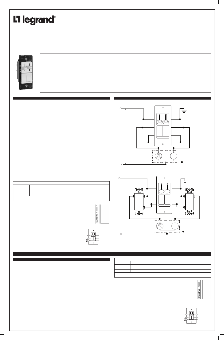
Legrand LSCLDCPBK User Manual Catalog Number(s) • Numéro(s) de Catalogue • Les Numéros de Catálgo: LSCLDCP. Country of Disconnect power to circuit by removing fuse or turn circuit breakers OFF.
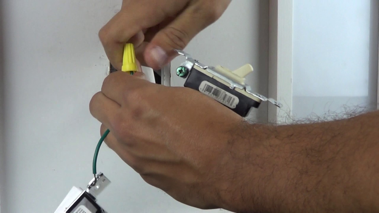
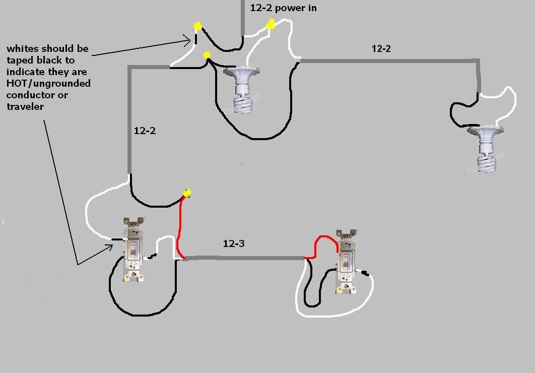
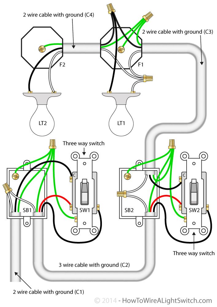
b. Now in the diagram above, The power source is coming in from the left.
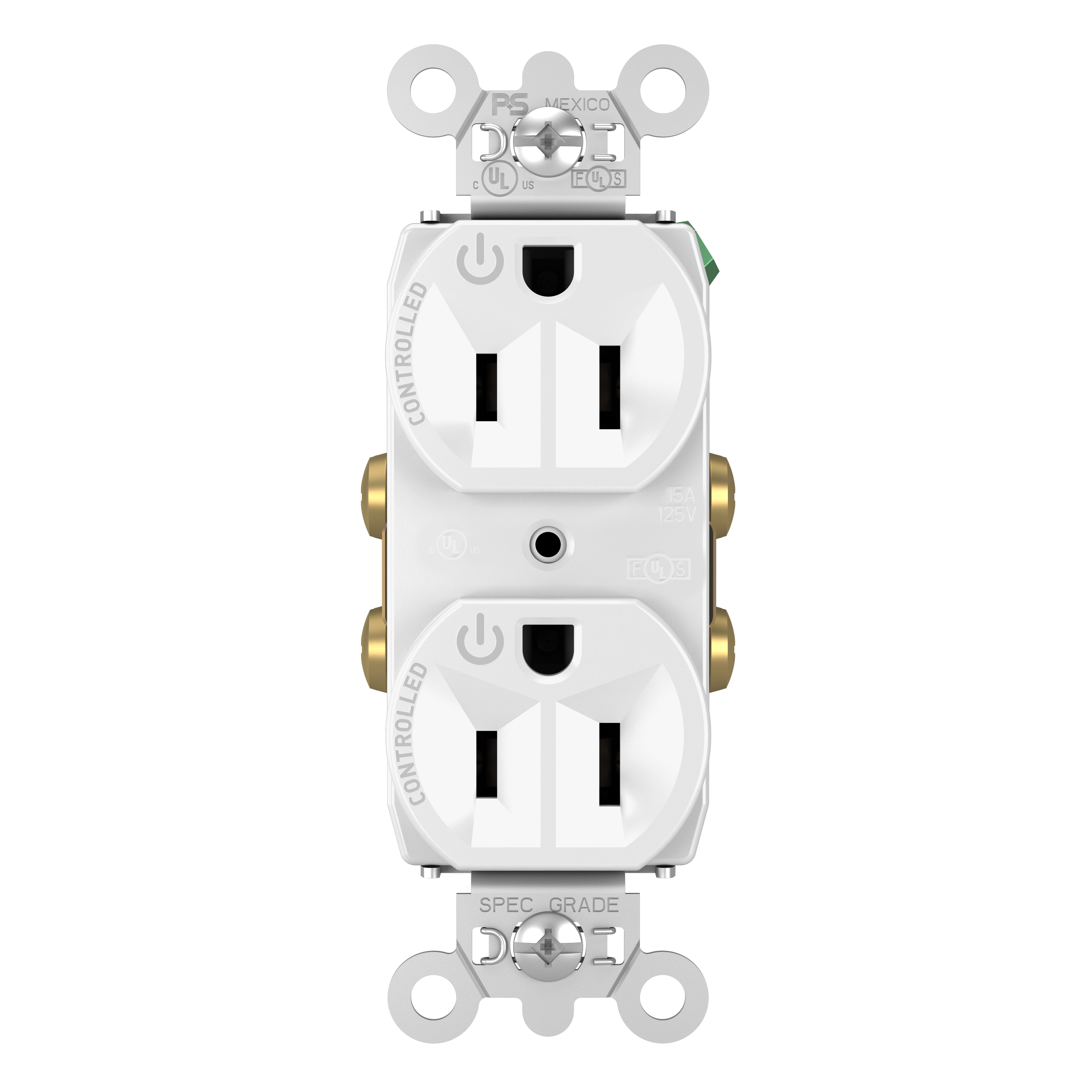
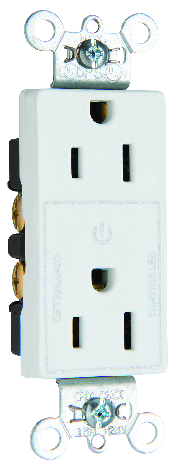
Notice the black wire is the only wire that we are controlling through the 2-way switch. 11 TOGGLE PRESET DIMMERS Convenient preset dimming control Combines replaces standard P&S toggle switches No loss of setting during power outages RFLC CFL/LED; W LSCLDCP** CFL/LED/, Dimmer with Single Pole/3-Way, Two Wire, Preset Adjustable Trim, Non-Preset Ivory, Light Almond, V.
Items 1 – 60 of Locking Manual Controller Switch LA. Call for price. Available: Incandescent Dimmer and Fan Control LSCLDCP.
Call for price. LS TradeMaster® Single-Pole/3-Way Preset Dimmer w/ Single-Pole/3-Way, 3- Speed De-Hummer Fan Control, Brown.
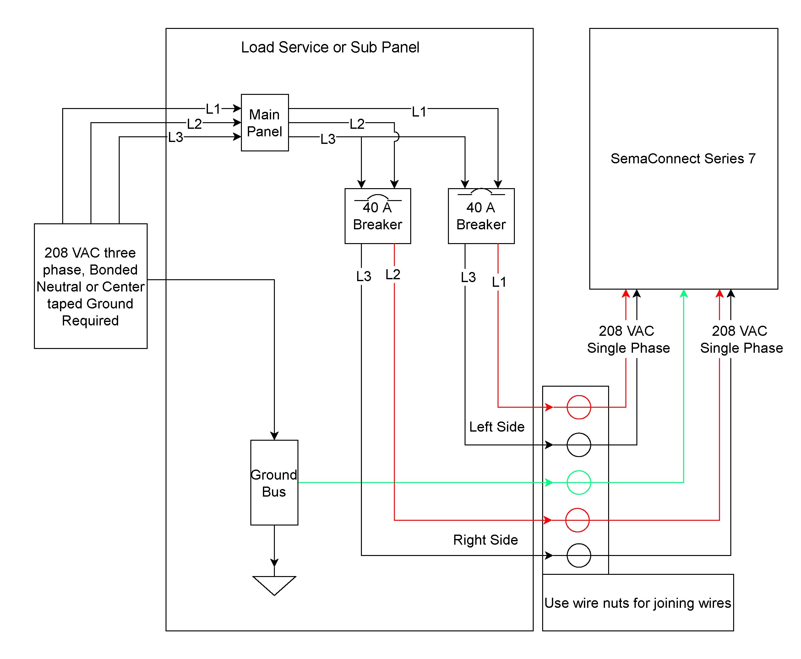
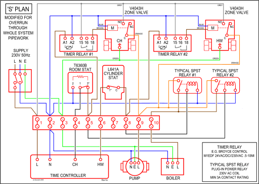
LSCLDCP | Pass & Seymour.3. Refer to appropriate wiring diagram. Connect unit to ballast and lamp leads per wiring diagram.
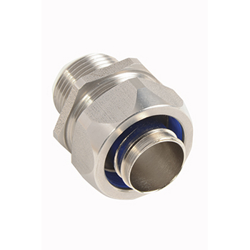
Note: A 7/8″ dia. conduit entry hole may be required to access lamp/ ballast and AC power wires.
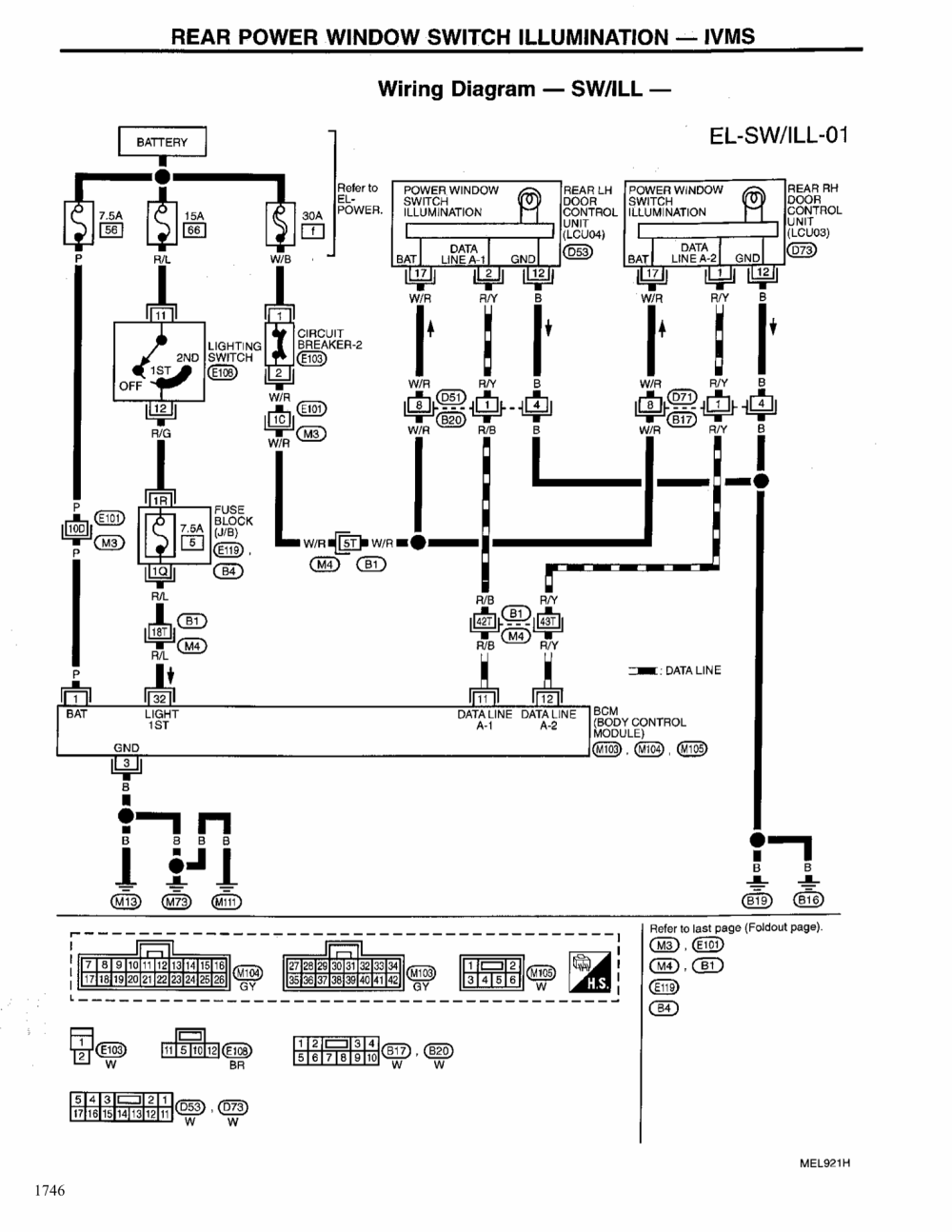
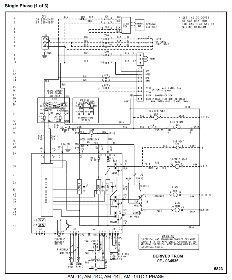
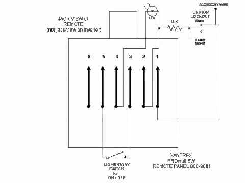
INVERTER INSTALLATION AND WIRING 2. Feed PSDL3 flex conduit through corresponding hole in external wireway cover. Attach appropriate. Switch wiring for volt or volt motors see Section and for Power Unit Test Diagrams with Limit Switches see Section AC Voltage Limit Switch Wiring Diagram Limit Switch Wiring Upper Limit Lower Limit Lower Safety Upper Safety Yellow White Black Red Red White Green Oran g .
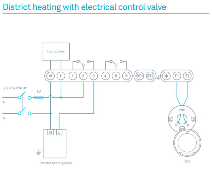
Many Bypass Switching Options. There are many variations in bypass switch wiring and in stompbox power connections.
We will attempt to cover these variations on this page. Let’s start with the power connections for your stompbox.
The most common power connections for stompboxes are covered in this Power Switching Article. Please read the article. a.
Disconnect power to circuit by removing fuse or turn circuit breakers OFF. b. Install a switch instead of the fan speed control.
Turn the switch to the “ON” position. c. If the fan fails to turn ON and OFF with the switch, the wiring may be incorrect. d.
Correct wiring, if necessary and retest. e.
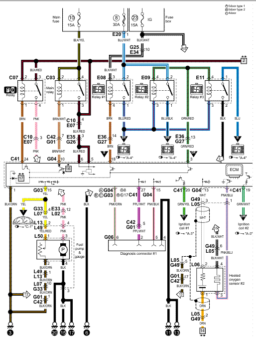
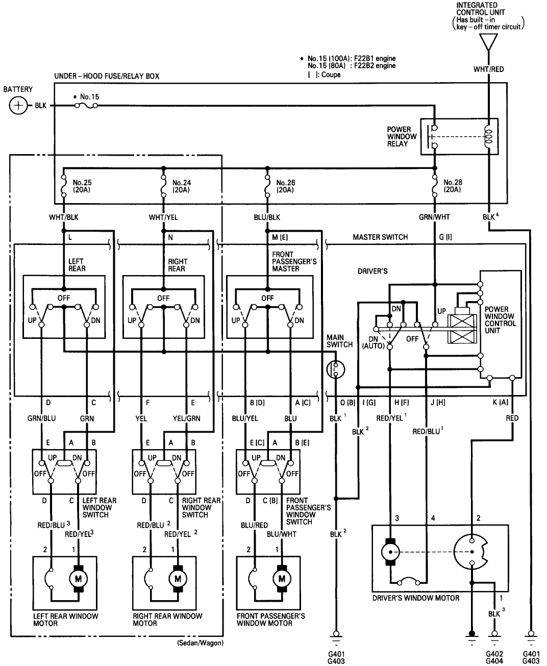
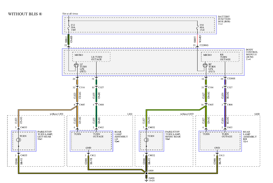
The following switch diagrams illustrate the most common types of toggle and rocker switch. Switch Diagrams.
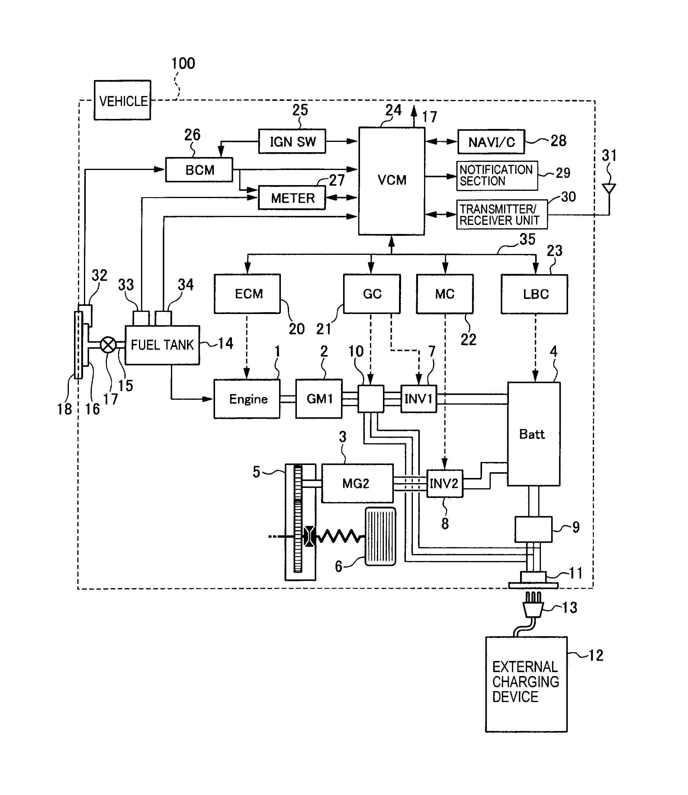
oecil Vehicle Pouct Dtsheet ittelfuse Commercial ehicle Products Diagram A Diagram B Diagram C Diagram D Diagram E Switch Wiring Diagrams Diagrams represent both momentary contact or maintained contact switches. Switches with.Wiring a 2-Way SwitchMany Bypass Switching Options | General Guitar Gadgets
