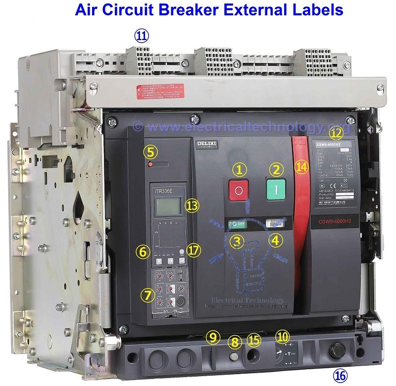
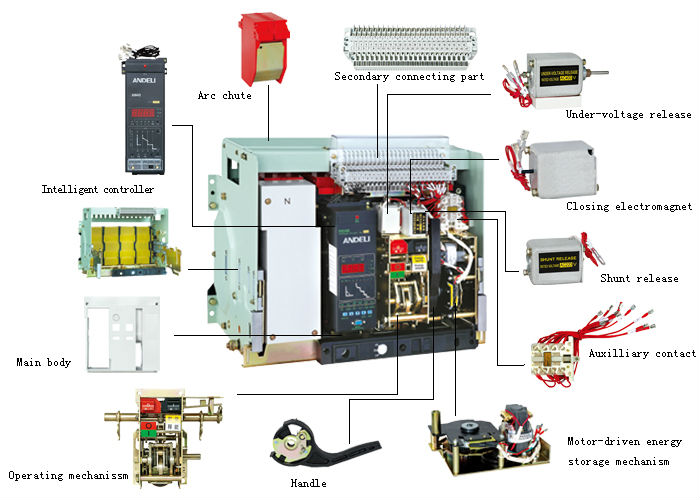
Spare Parts Manual bringing out an exhaustive listing of spares that any ACB user may ever need to maintain his Air Circuit Breakers in good shape.
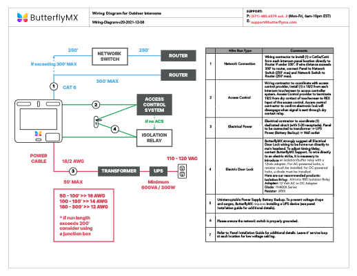
Eaton Wiring Manual. Chapter. Eaton Wiring Manual.
0. Switching, control, visualization.
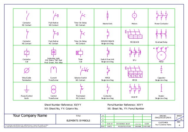
1. Electronic motor starters and drives. 2.
Pilot devices. 3.
Cam switches. the Accessories of the C-POWER Air Circuit Breakers, please refer to page 55 of the L&T manual.
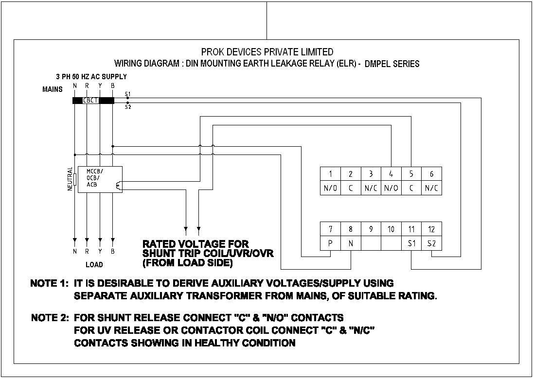
Vertical Terminal Adaptors for Draw out C-POWER ACB. NHP MOD power ACB’s Undervoltage release has a special feature, Trace the Control circuit wiring based on panel wiring diagrams given by the ..
It is recommended to call L&T’s Authorised Service Centre for servicing the breaker. V L&T Make Air Circuit Breaker Details 04 2.
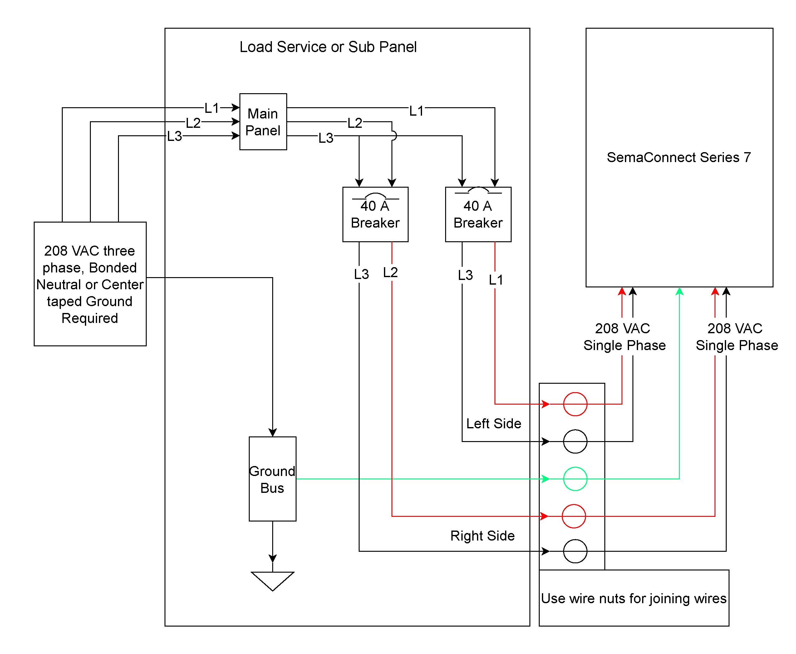
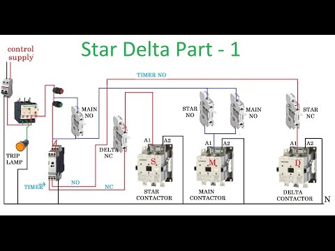
In case of manual reset type ACB actuation of TRIP push button / key of lockable trip push.Introduction to Control Theory Including Optimal Control Nguyen Tan Tien – Rotational Mechanical Systems Block Diagrams Signal Flow Graph Method Block Diagrams and Transfer Functions Block Diagram:Used to represent composition and interconnection of a system. C-POWER Air Circuit Breakers -POWER ACB Breaker control through MODBUS protocol For technical & dimension details please refer product catalogue.
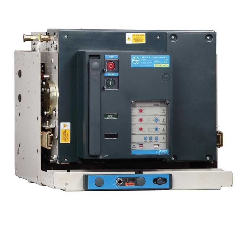
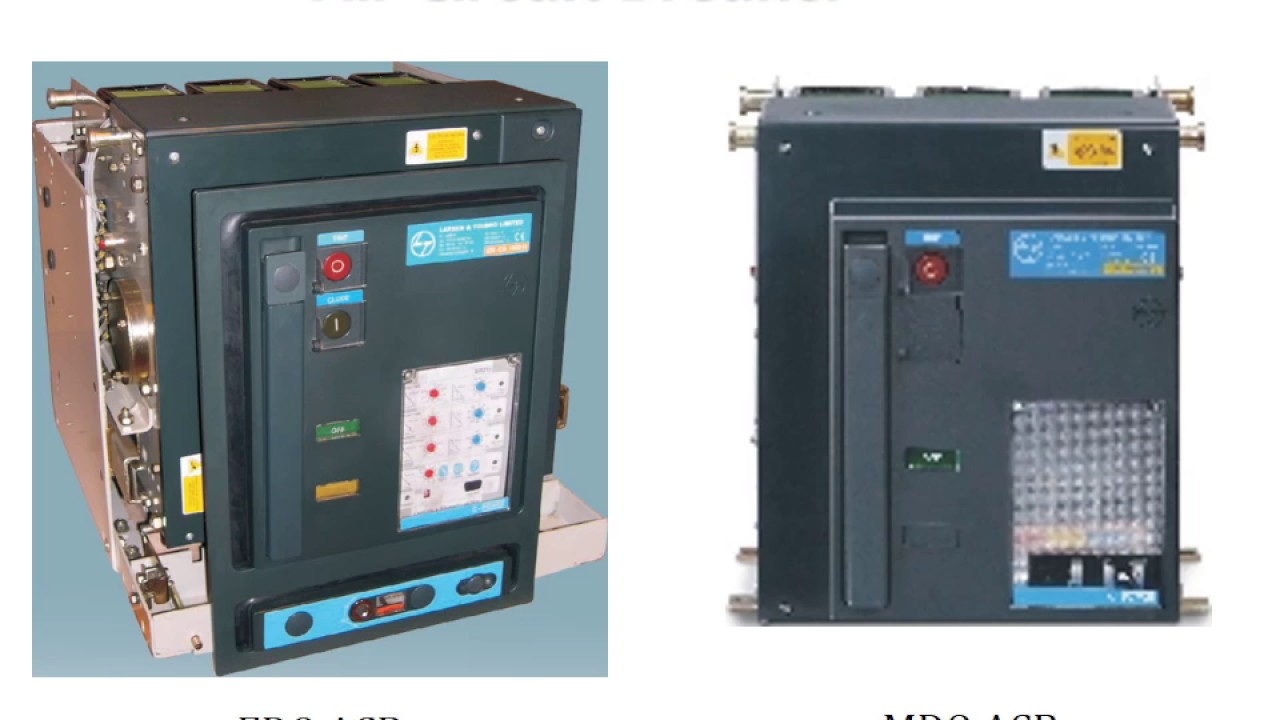
A ACB also available on request. L&T, ESP C-POWER Air Circuit Breakers C -POWER S1 3 & 4 Pole Draw-out ACBs.
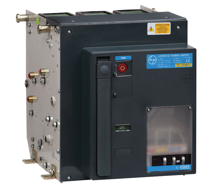
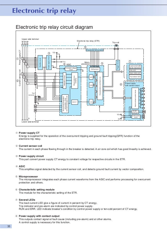
Air Circuit Breaker W/ 24 vdc shunt trip, vac spring release, and the wiring diagram is 1A Mounting the ACB in such an area could cause a fire or malfunction. L&T SWITCHGEAR ESP SERVICE MANUAL Internal connections of the DN release with CT is shown in the following diagram.
OVERLOAD TESTING INTERNAL WIRING DIAGRAM OF NEW DN RELEASE CT R Phase CT Y Phase CT B Phase T1 M1 T2 M2 T1 M1 T2 M2 T2 M1 T2 M2 S O / L Bime xxx SC Magnetic C xxx Shorting link for fixing E/F release. l Be sure to read this manual before installing, operating, servicing, or inspecting the ACB.
l Please retain this manual for future reference. l Electrical work must be done by competent persons.
l ACB maintenance, inspection, parts replacement, OCR field tests and setting changes must be performed by competent persons.Buy L&T Switchgear ACB at Online in India |schematron.orgHow to Wire a Contactor: 8 Steps (with Pictures) – wikiHow