Jul 26, LT1 Reverse Flow Cooling System By Scott Mueller.
One of the greatest features of the ’92 and up Chevrolet LT1 engine is the reverse flow. LT1 Reverse Flow Cooling System By Scott Mueller. One of the greatest features of the ’92 and up Chevrolet LT1 engine is the reverse flow.
Chevy reversed the flow direction in the LT1-LT4 engines to direct the cooling system can easily over come. the direction of coolant flow is not .
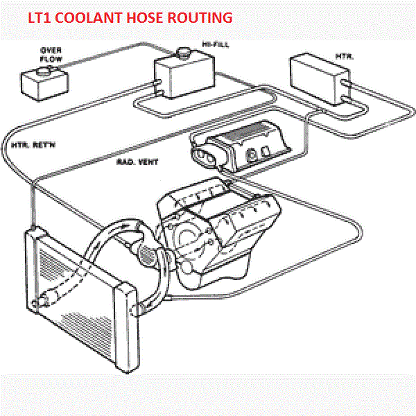
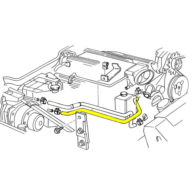
all coolant flow paths roughly equal in the crappy diagram below the blue. In , GM introduced the LT1 engine, a revolutionary new CI small block to be used in all its rear wheel drive vehicles. All of these engines from through use a reverse flow water pumps that is driven directly off the camshaft.
The reverse flow water pump utilizes. Sep 11, The Chevrolet LT1 L V8 engine that was produced from to reverse-flow cooling system and mass airflow sequential fuel.LT1 Reverse Flow Cooling System By Scott Mueller.
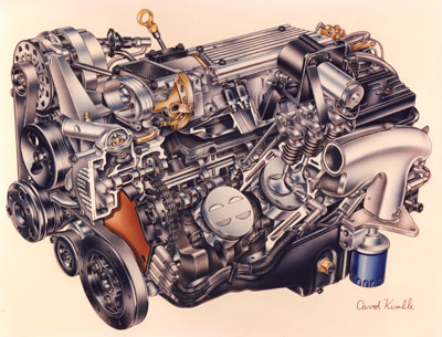
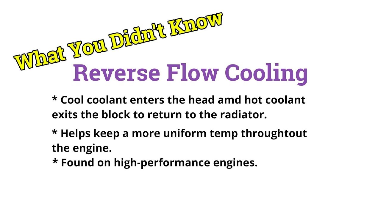
One of the greatest features of the ’92 and up Chevrolet LT1 engine is the reverse flow cooling system. In fact it is reverse flow cooling that is truly the key to the incredible performance of the modern LT/5(7).
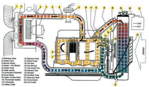
LT1 Reverse Flow Cooling System By Scott Mueller. One of the greatest features of the ’92 and up Chevrolet LT1 engine is the reverse flow cooling system. In fact it is reverse flow cooling that is truly the key to the incredible performance of the modern LT1.
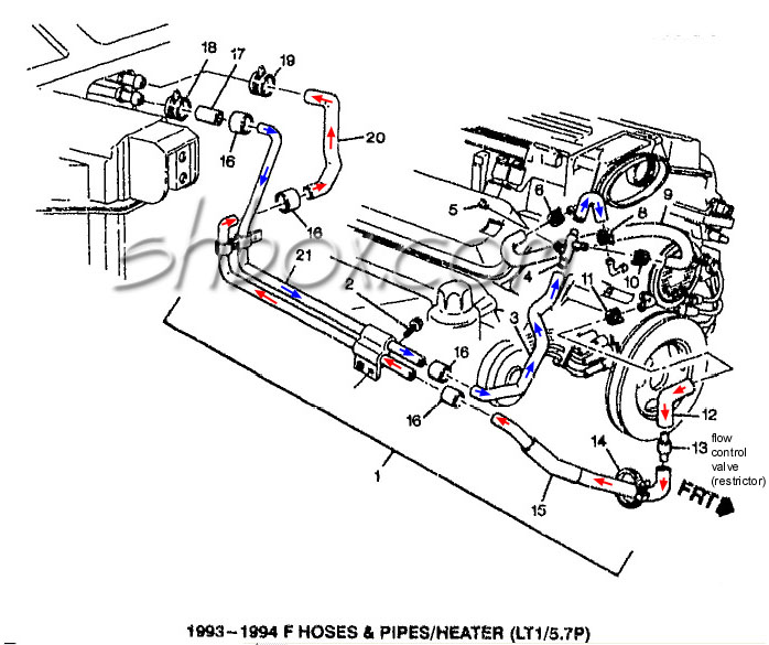
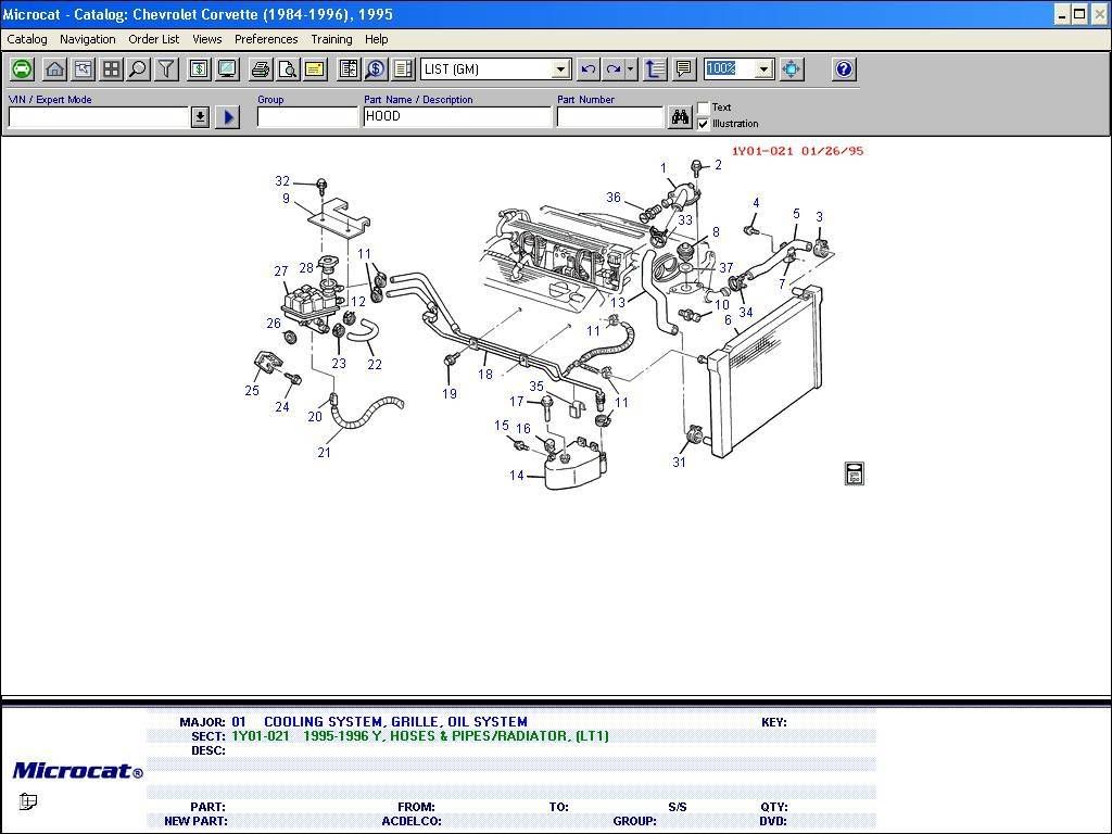
Mar 13, · C4 Tech/Performance – I need LT1 reverse flow diagrams/pictures of the coolant system. – Hi guys, i need any kind of diagrams or pictures or any info about the reverse flow cooling system found on the LT1 engine for a school course that i am doing.
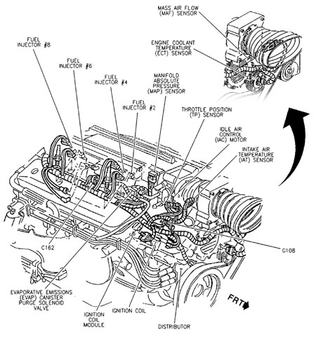
Thanks a lot for your time. 4th Gen LT1 F-Body Technical Aids Diagrams Drawings Exploded Views Optispark Venting Diagram; Optispark Mounting Exploded View (vented) Exhaust System Exploded View (single cat) Exhaust System Exploded View 95 RPO NB6 & (dual cat) Convertible Top Pump. Aug 07, · The thermostat is on the suction side of the water pump, unlike a traditional V8.
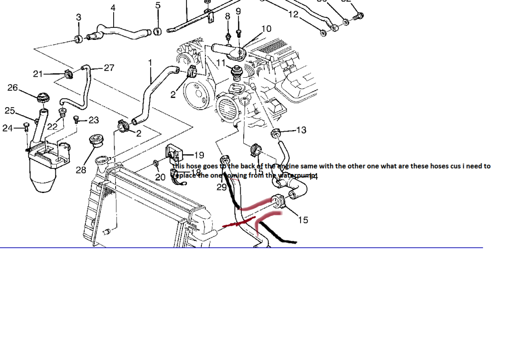
This really has nothing to do with the “reverse flow” cooling system, they just put the thermostat in a different place. LS1 engines are “standard flow” and they also have the thermostat in the suction line.How the Cooling System Works- Corvette: Technical Article: LT1 Reverse Flow Cooling System
