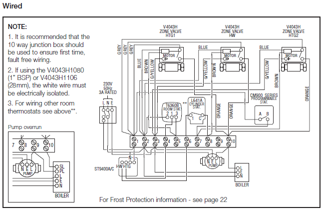
WIRING DIAGRAM. W. G.
B. R. BK.
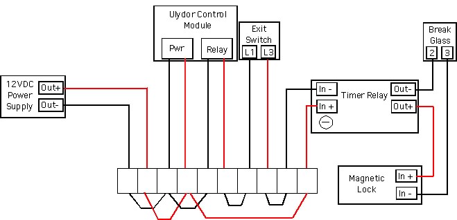
BN Diagram shows normally energised Magnetic Lock. PUSH TO EXIT Break Glass Inputs are not used, they should be.
Forgot to say break the “+” to the mag lock in the green break glass unit. A lot of people break the power from the power supply, not really a.
Example Strike lock wiring. Example DC Magnetic lock wiring. -.
+. Break.
Glass. D/C.
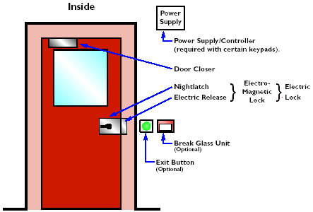
PSU for lock. Exit Button. Optional emergency break glass unit. v dc.
CONNECT DIRECTLY TO. EMERGENCY BREAK GLASS.
IF YOU ARE NOT USING A. ULYDOR PRODUCT TO. REMOTELY UNLOCK DOOR.
ADJUST VR1 . Connection of magnetic lock using supplimentary power supply.
Date. Installation The additional power supply is connected with the least number of wires by linking the negtive (-ve) of 1. 2.
5. 6.
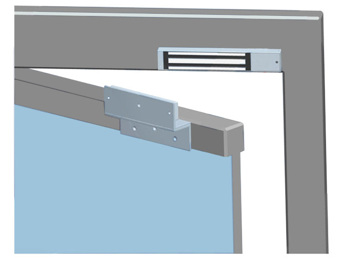
D Resettable break glass unit .Maglocks can be used on hollow metal, wood, aluminum, glass and composite door materials. The UL Listed Maglocks are available in surface mount single or double door configurations, with holding force of or 1, lbs.
These locks include adjustable sec relock time delay and a . > Magnetic Lock Setup Guide Introduction.
Magnetic lock systems are fairly simple to set up. This guide will take you through the basics of connecting the components together.

It will give you a general idea of how the wiring should be completed, while leaving out details such as . This Deedlock access control kit includes three devices that enable entry and exit from a building by activating an electromagnetic lock.
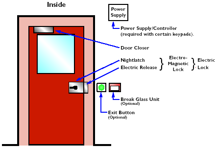
Sited at the top of the door, the electromagnetic lock can be released in three ways; entering the correct code into the keypad entry system, pressing the white exit button or activating the emergency call schematron.org: £ Sep 12, · Description: 30 Beautiful Fire Alarm Break Glass Wiring Diagram – Pixelmari for Break Glass Wiring Diagram, image size X px, and to view image details please click the image.. Here is a picture gallery about break glass wiring diagram complete with the description of the image, please find the image you need.
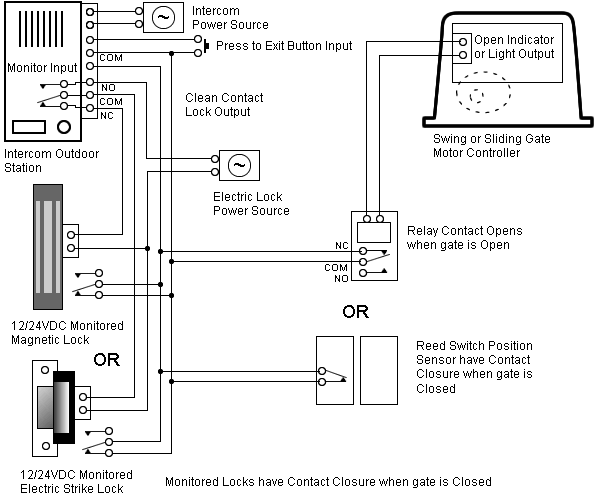
MAGNETIC LOCK INSTALLATION INSTRUCTIONS A terminal block is provided for wiring the maglock to the power supply and for the Bond Sensor Relay outputs. A pair of flying leads are provided for the Door Status Sensor (Reed Switch).
These are the Green and White wires.LocksOnline Wiring Diagram | Locks OnlineCommon wiring diagrams