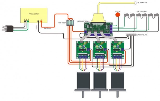
Equipped with effective MOSFET H-bridge-based motor driver module IC When the Dupont wire is used to connect the module to the Arduino UNO Baseboard, its SCL and SDA pins should be connected to I2C port, that is, Schematic.
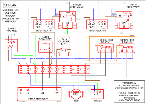
The Me Stepper Motor Driver module is designed to precisely drive the It can be used in 3D printing, numerical control, Makeblock music Provide grounding short-circuit protection and loading short-circuit Schematic. MegaPi is a main control board specially designed for makers and also an ideal option for being applied to Four motor driver interfaces for adding encoder motor driver and stepper motor driver, and thus to drive Schematic Circuit Diagram.
The Me Stepper Motor Driver module is designed to precisely drive the It can be used in 3D printing, numerical control, Makeblock music Provide grounding short-circuit protection and loading short-circuit Schematic.
Dec 6, Both the Makeblock Orion board and the Makeblock Orion Shield are populated with RJ25 jacks. a motor module with a red sticker can connect to the board at a port with a install Arduino IDE , Arduino Drivers if necessary, and ArduBlock.
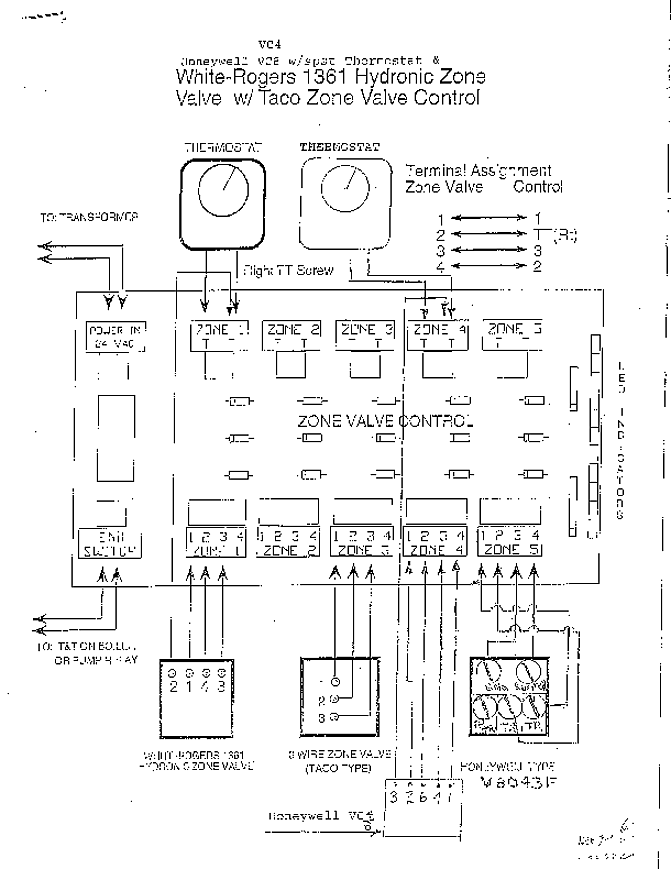
Connection diagram from inside the mDrawBot program.The Me DC Encoder Motor Driver needs to work with encoder motor. The major difference between encoder motor and DC motor is the motor rotation feedback, which is achieved by encoder.
Currently, there are 2 types of encoder: magnetic encoder and optical encoder. Being fixed on motor shaft, the magnet ring or coding disc will rotate with the motor.
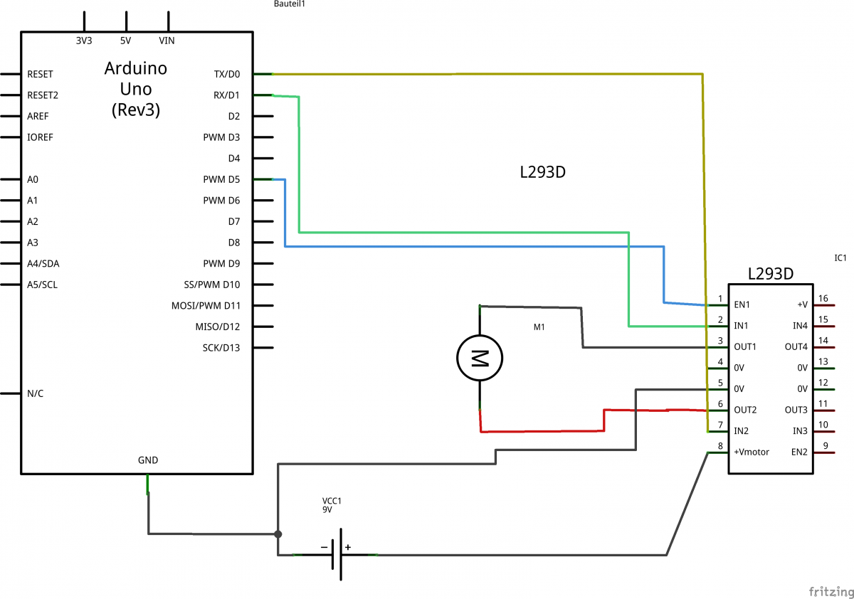
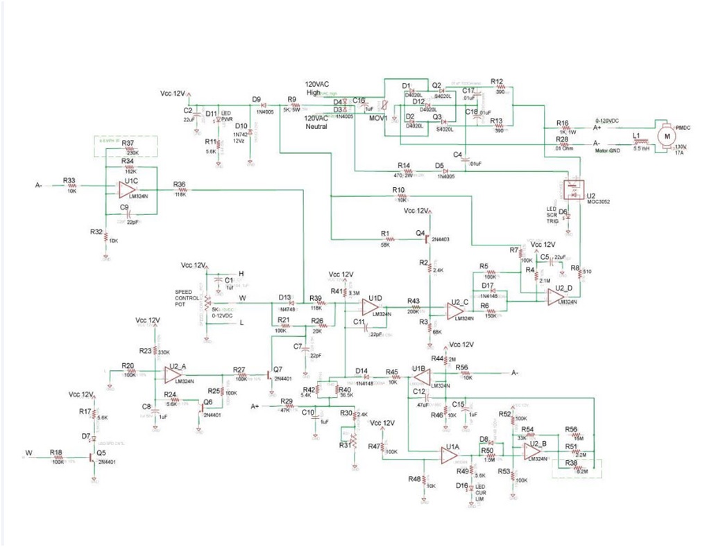
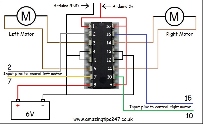
Jun 10, · The Me high power is supposed to connecting to makeblock mainboard through the RJ25 port. As for connecting to to arduino board, we don’t have such instruction. I have sent you a circuit schematic of the Me high power encoder motor driver to your email address, hope you can figure out the connections for the pins between the driver and arduino.
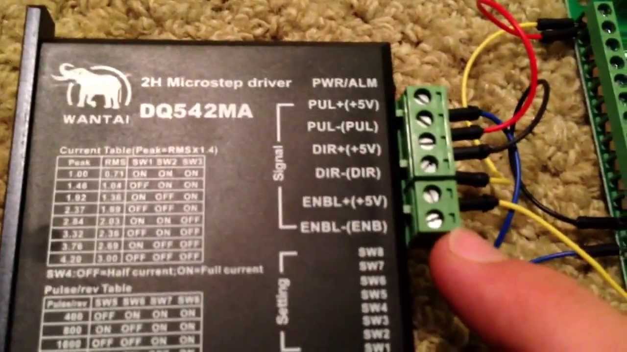
The Stepper Motor Braket is not included. Connection Type. May you are confusing about which color cable on the stepper motor should be connected to which port on the driver (A+,A-, B+,B-), Here is a guide of it. 1.
Ourstepper motorhas two phase. So it doesn’t matter you change the connection order between phase A and phase B. The motor driver voltage is from 9V to 35V, and includes on-board 5V/V regulation, so you can directly connect it to Me-Base Shield on Port1 or Port2 without any other power supply.
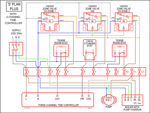
We also reserved a power supply connector on the board; you can also use an extra power supply for it. Makeblock Music Robot V User Guide schematron.org 27/40 3 Music Robot Kit V Electronic Wiring Guide Connect the Me Ultrasonic Sensor V to Port 3 of Me Orion. Connect the Me Stepper Motor Driver to Port 1 of Me Orion.
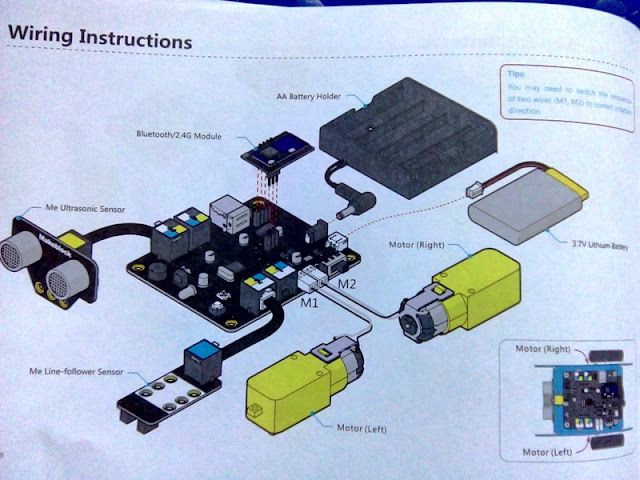
Connect the DC Frame Type Solenoid to Port M1. Connect the Me RJ25 Adapter V to Port 6.Connecting High-Power Encoder Motor Controller with Arduino – Makeblock Products – Makeblock ForumMakeblock: Global STEAM Education Solution Provider
