8 Cylinder Applications With COMP Cap 87 Series.
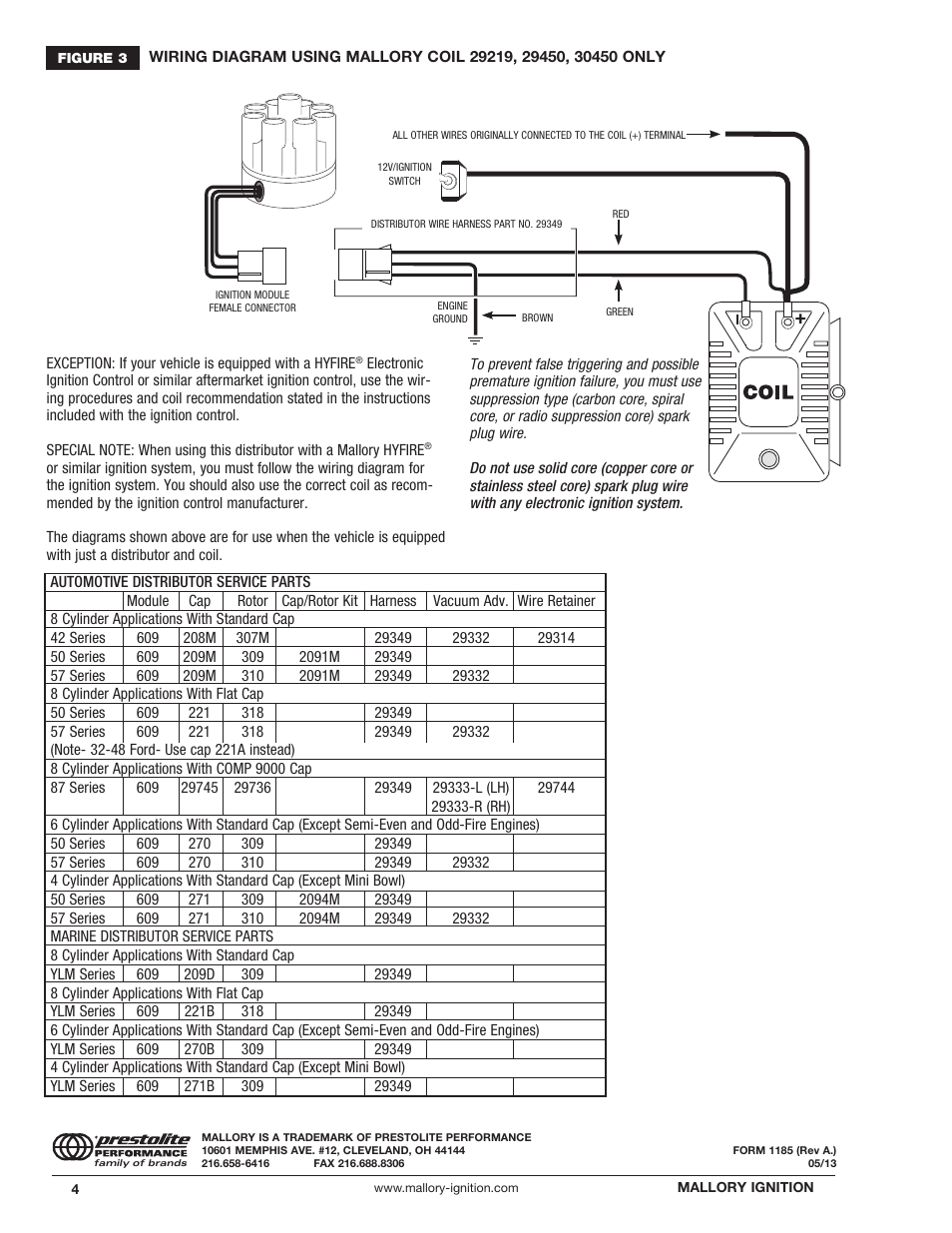
WIRING DIAGRAM USING MALLORY COIL , , ONLY. EXCEPTION: If your.
v8wizard rh v8wizard com sbc mallory distributor wiring diagram mallory mallory comp wiring diagram inspirational mallory pro p rh. Sbc distributor wiring diagram mallory distributor wiring diagram mallory comp unilite wiring diagram wiring solutions mallory dist wiring. WARNING: Mallory’s Magnetic Breakerless Ignition System is not compatible with positive ground or.
6-volt vehicle . WIRING DIAGRAM USING OEM PRIMARY ( LOOM) RESISTANCE WIRE 8 Cylinder Applications With COMP Cap.
(magnetic pickup distributor or crank trigger). NOTE: This ignition COMP Distributors. Wiring tor and coil in the wire from the ignition switch (see diagrams for more infor- mation on lem, install Mallory’s Fuel Injection/Tach Adapter Part No.
. Special wiring harnesses simplify the installation of the HYFIRE® ||IA.Jun 15, · As for wiring it in, you do could desire to have a lot of wisdom on wiring diagrams and which wires to delete. of course a number of those Mustang components places could have wiring kits that make setting up FI a lot less demanding.
that’s the simplest thank you to schematron.org: Resolved. A simple three-wire hookup that makes it easy to run a stock coil, Mallory coil, or Mallory HyFire CD ignition.
Read More. see more Mallory news Mallory to MSD Cross Reference Guide.
Mallory Service Part Guide. Stay tuned as we bring Mallory ignition and distributor lines back!
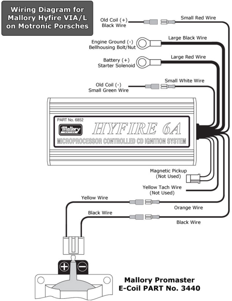
About Us. Mallory Msd Box Wiring Diagram from mallory comp wiring diagram.
Hook them up per instructions and you ought to be all set. It looks to be a simple approach.
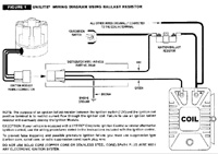
2 schematron.org MALLORY IGNITION-+ COIL FIGURE 1 UNILITE® WIRING DIAGRAM USING BALLAST RESISTOR NOTE: The purpose of an ignition ballast resistor between the ignition switch (12V) and the ignition coil positive terminal is to restrict current flow through the ignition coil. Failure to use an ignition ballast resistor will. wiring diagram using ignition ballast resistor all other wires originally connected to the coil (+) terminal 12v/ignition switch ignition ballast resistor red distributor wire harness part no.
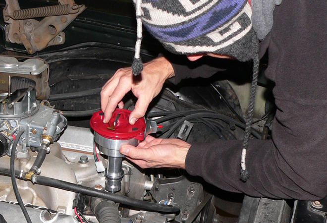
Failure to use resistance wire will eventually destroy the Ignition Module.Mallory Ignition Mallory MAGNETIC BREAKERLESS DISTRIBUTOR User Manual | Page 4 / 4mallory distributor p/n – Hot Rod Forum : Hotrodders Bulletin Board