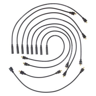
Mallory’s PROMASTER® Coil P/N can also be used, as well as most stock NOTE: Do not use solid core spark plug wires with the HYFIRE®. 6A Ignition ..
of the following diagrams fit your specific application, remove the distributor. WIRING PROCEDURE.
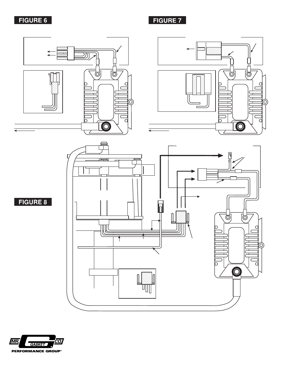
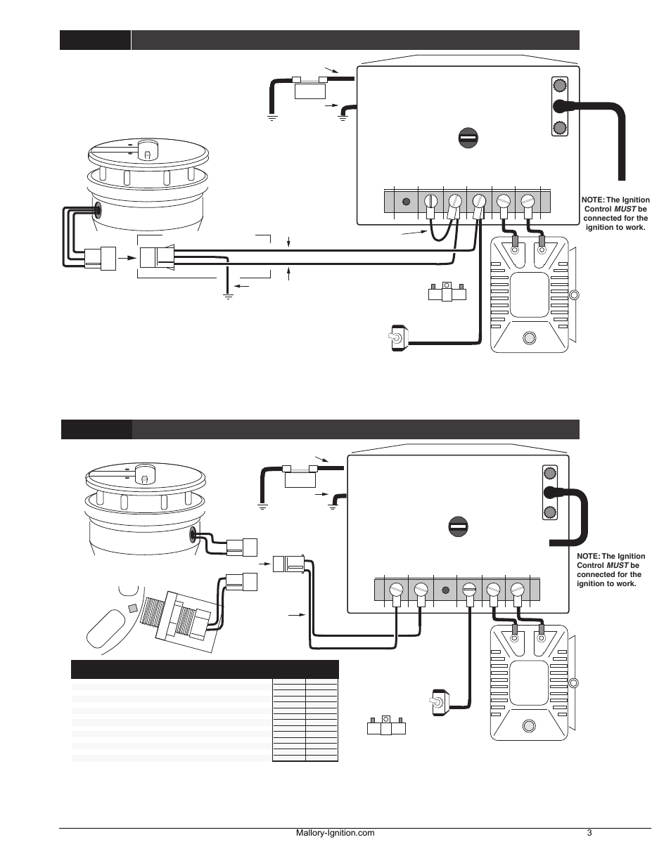
See pages 2 and 3 for wiring diagrams and information. NOTE: If you are using an aftermarket ignition control, such as a Mallory. See pages 2 and 3 for wiring diagrams and information.
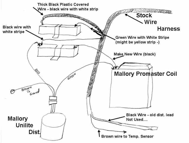
NOTE: If you . INTERCHANGE A PROMASTER® COIL WITHOUT CUTTING WIRES (SHOWN BELOW). Promaster, Ignition coil, Installation instructions • Read online or download PDF • Mallory Ignition See pages 2 and 3 for wiring diagrams and information.

mallory promaster coil wiring diagram wiring library rh 15 yoobi de Mallory Marine Ignition Wiring Diagram Mallory Unilite Ignition Wiring.Fold the core over the outside of the coil wire. Step 2.
Put the coil wire terminal on the end of the coil wire and crimp the connection. Step 3. Slide the coil wire into the coil wire boot.
Install the coil wire on the high voltage terminal. See Figure 1.
WIRING PROCEDURE. See pages 2 and 3 for wiring diagrams .

use a Mallory PROMASTER® Coil Part No or , or Mallory PARTS INCLUDED IN THIS KIT:1 UNILITE® Distributor 1 Distributor Wire Harness IMPORTANT FIGURE 3 WIRING DIAGRAMS USING AFTERMARKET ELECTRONIC IGNITION CONTROLS-+ COIL MSD™ 6 SERIES IGNITION PART NO. Mallory unilite wiring diagram and coil as well as positive ground distributor diagram in addition mallory ignition distributor wiring diagram moreover dual tachometer wiring diagram along with msd electronic ignition together with mallory promaster coil wiring diagram as well as mopar electronic ignition module along with hei dist wiring. Mallory Promaster Coil Wiring Diagram Best Of Mallory Coil Wiring Diagram Download.
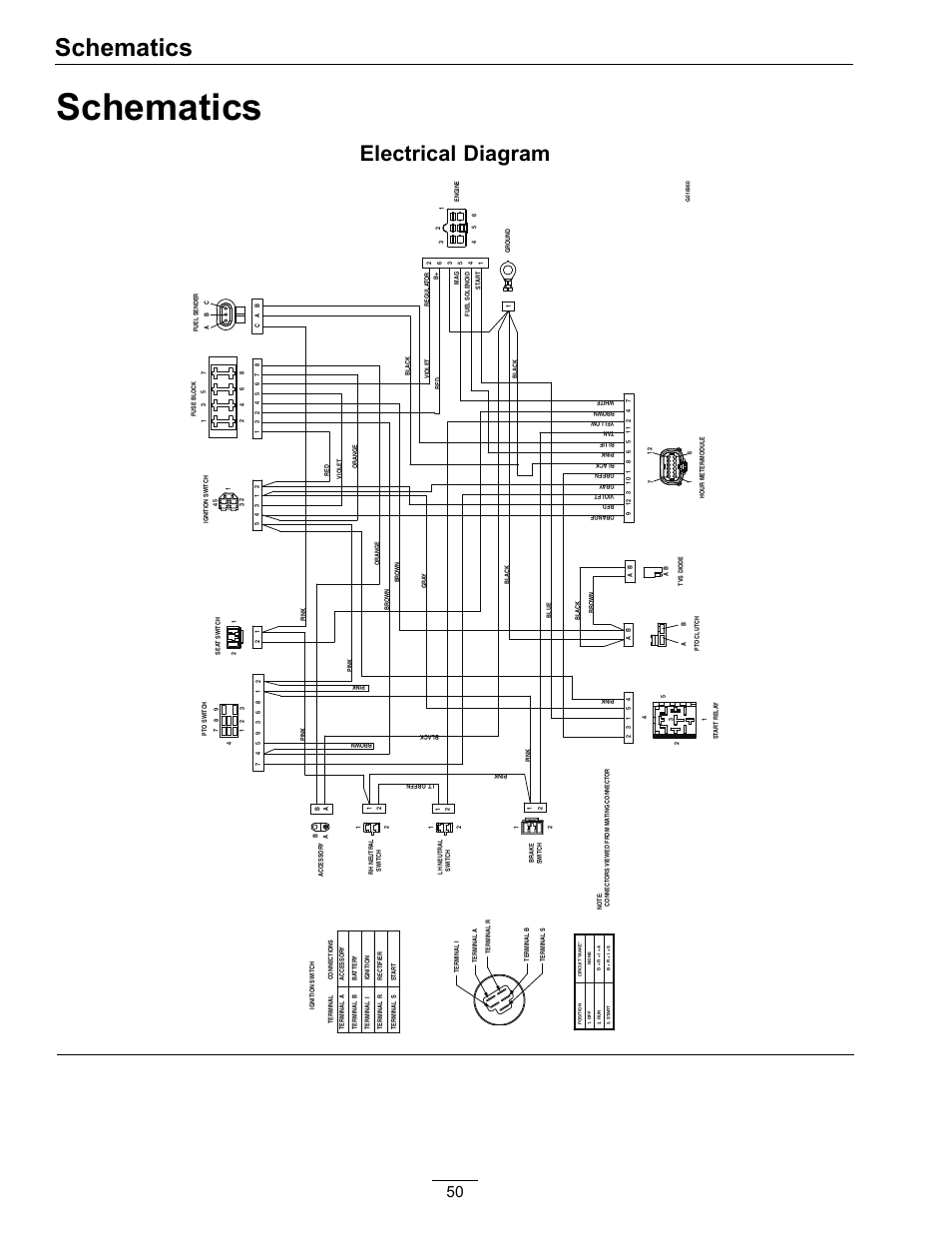
Coil Wire Diagram – coil wiring diagram – I need a wiring diagram. for coil i have replace the motor i did not mark the wire going to the coil. the way i have it hooked up n.
May 21, · Finally finishing up the wiring on the ’54 Wagon and I ran unto a snag. the outside of the coil wire. Step 2 Put the coil wire terminal on the end of the coil wire and crimp the connection.

Step 3 Slide the coil wire into the coil wire boot. Install the coil wire on the high voltage terminal.
See Figure 1. WIRING PROCEDURE See pages 2 and 3 for wiring diagrams and information.OLE BLUE: First look under the Hoodwiring diagram for mallory schematron.org – Hot Rod Forum : Hotrodders Bulletin Board
