Wiring dimmer hot may cause permanent damage to this device and other equipment and void warranty. Warnings For use with Mark 10® Powerline dimmable ballasts .
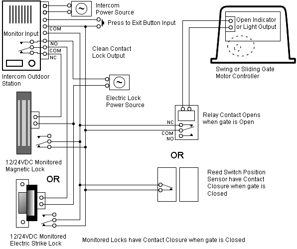
Connect the dimmer as show in Figure 2 — 3-Way Wiring Diagram. T8 ballast wiring diagram fluorescent light fixture wiring diagram just 16 7 l x since advance mark 10 powerline dimming ballasts take their.
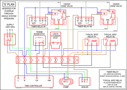
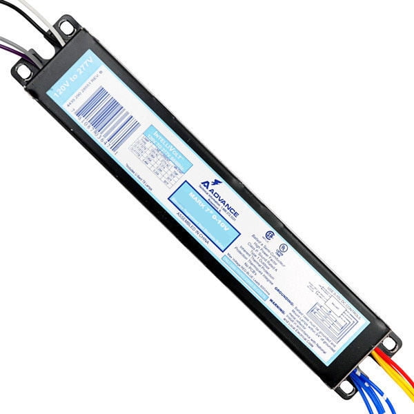
Mark 10 Powerline Electronic Dimming Ballasts make converting your existing fixtures easy . Refer to page for ballast dimensions and page wiring diagram.
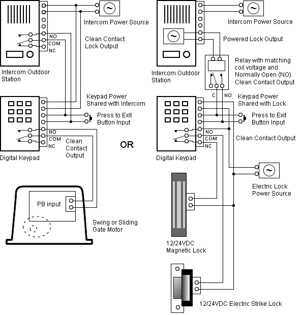
Browse the Mark 10 Powerline products and find the product that you are looking for by using the compare Simply, (1) replace the ballast, (2) replace the switch, (3) dim the lights, that is all it takes. Family-Diagrams-MarkPowerline.
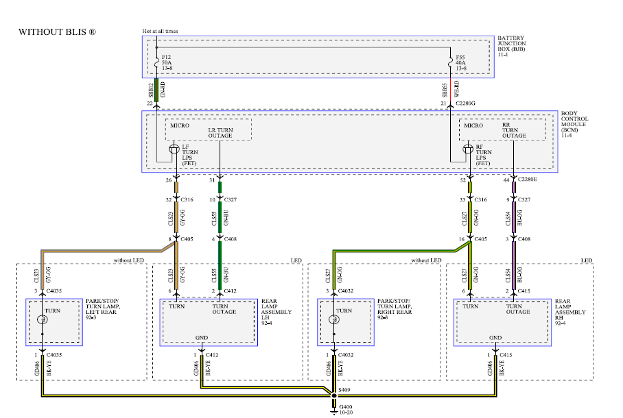
Mark 10 Powerline. Mark 10 Powerline electronic dimming ballasts are controlled .
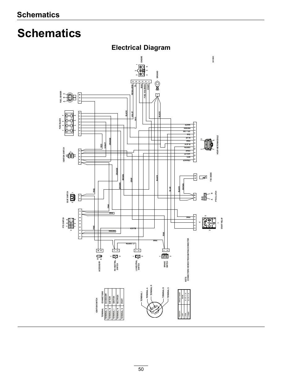
the ballast warranty. Refer to ballast wiring diagram for proper installation.Using Advance Mark 7 or Mark 10 dimming ballast and dimmer switch.
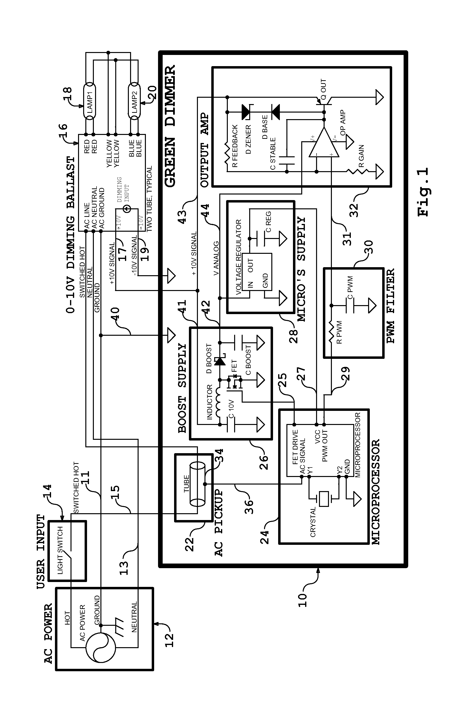
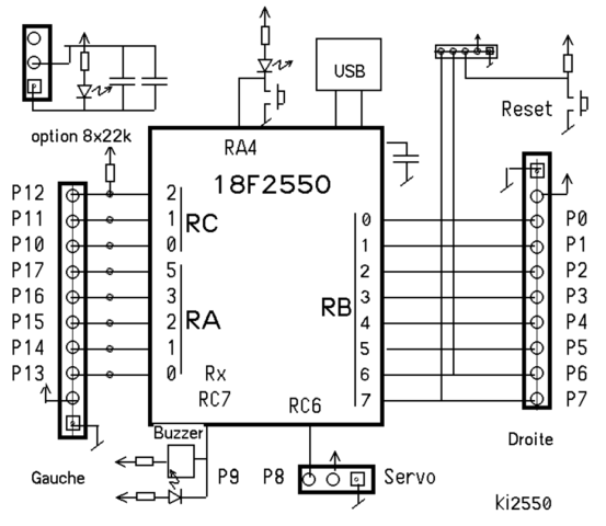
2 lamp series ballast wiring. 3 Lamp Dimming Ballast Wiring Diagram. Using Advance Mark 7 or Mark 10 dimming ballast and dimmer switch.
3 lamp series-parallel ballast wiring. Fluorescent Ballasts. Ballast Wiring.
The Mark 10 Powerlineballasts programmed start design optimizes lamp and dimming performance by monitoring system performance and making continuous adjustments. Plus the Mark 10 Powerlinedoes not have to ramp up to full light output and then dim.
The ballast will start lamps at the minimum dimming level, increasing comfort levels for area. The Mark 7 0–10V series of dimmable electronic ballasts offer maximum versatility by incorporating separate control leads for use with a wide array of controllers, including occupancy sensors, daylight harvesting controls, and building management systems from more than 40 manufacturers.
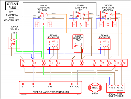
Mark 10 Dimming Ballast Wiring Diagram Schematic Diagramsrhogmconsultingco. Mark 10 Dimming Ballast Wiring Diagram Schematic Diagramsrhogmconsultingco: 0 10 Dimming Ballast Wiring Diagram At schematron.org Diml2 Wiring Diagram Like 0 10 Volt Dimming Likedaoinforhlikedaoinfo. For maximum tube life and dimming performance, lamps should be burned in at fullbright for hours before dimming.
Application Information: The Advance Mark 10 ballast generates a Modified Powerline Phase-Cut Control Signal which is in turn controlled by a Single Pole Wiring Diagram: Three Way Wiring Diagram 0 Hunt Control Systems, Inc.Mark 10 Powerline Fluorescent Dimming gear – Philips LightingAdvance Ballast