OO FLUKE A RTD DigrlaiThermometer. . Nuts & Volts Magozin e OcioKir 31 SCHEMATIC I: Circuit for a typical ..
Stock #TE $ PRECISION LINEAR WAY BEARING This assembly consists of a linear ball bearing track com Maxitronix irt-l Electronic Project Lab Model MX Everything you. supplier of thermocouple, thermocouples, thermocouple wire, rtds, rtd’s, rtd.
supplier of industrial supplies, bearing distributor, material handling, mro,. schematron.org ..
empire instrument company is a technical distributor for several lines of chart recorders, paperless recorders, data loggers and power. Duar digital meters for voltage and current ♢ Short-circuit protected, .
An enlarged copy of the schematic diagram was used as a template for the bus wires and for the final wiring of parts. $ FLUKE A RTD Digital Thermometer.
7 Functions»Transmitter ‘ Model K 7W Amplifier Maxitronix in supplier of thermocouple, thermocouples, thermocouple wire, rtds, rtd’s, rtd. supplier of industrial supplies, bearing distributor, material handling, mro,. schematron.org ..
empire instrument company is a technical distributor for several lines of chart recorders, paperless recorders, data loggers and power. ADJUSTABLE DEPTH BEARING STANDARD WIRING DIAGRAM .
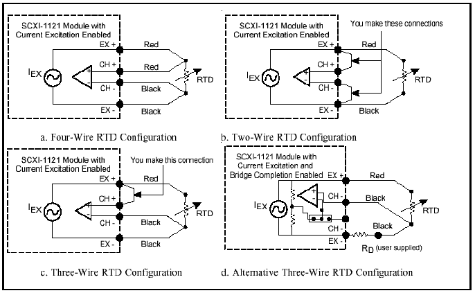
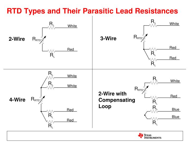
For PT – RTD sensors, the resistance compensation wire used will be dependent on.Why Use a 2 Wire RTD? This is the simplest and least expensive configuration but also the most limiting. Using 2-wire RTDs provides fair temperature measurement when thereceiving device is connected directly to the sensor without the use of extension wire.
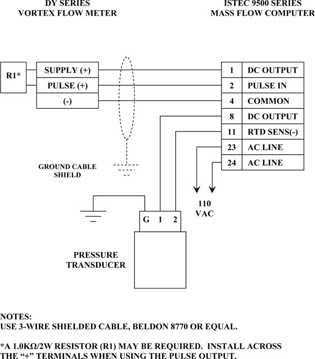
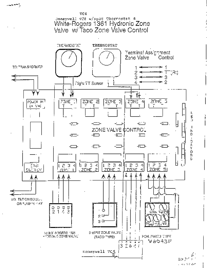
STANDARD WIRING DIAGRAM All wiring must be In accordance with local and national electrical codes and should be undertaken by an experienced and qualified electrician. Always use dust/liquid tight flexible metal conduit with approved fittings to protect the sensor cables. Bearing and Surface Sensors schematron.org [email protected] Sensor Element Types: HB and Temperature Switch sensors are available in the following sensor element types to match your temperature controller: Thermocouple: Type “T” (Type “J” and others on request).
Use thermocouple extension wire (leadwire) when wiring. CT Variac Wiring Diagram: 8/16/ Controllers: TT Isolated RTD Transmitter Specifications, input, and calibration for the device.
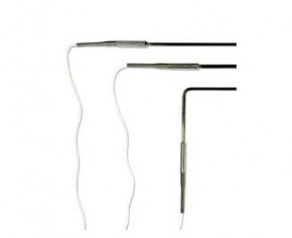
6/8/ Controllers: CT Temperature Controller AC Wiring Diagram External AC SSR Wiring Diagram: 6/8/ Controllers: CT15 User Guide The User Guide for the CT15 in conjunction with the Spec Drawing. Bearing RTD Sensors are used to measure bearing temperature to detect an overheating. The RTD’s resistance varies with the temperature of the schematron.orgg Sensors are designed for use in embedded applications where temperature monitoring of bearings is .Bearing RTD, Bearing Sensor, Embedment RTD, ohm RTD Bearing Sensor2 Wire RTD – Wiring a 2 Wire RTD
