Waltco Liftgate has a variety of switches for every model of gate. Each gate has at least one switch, but possibly two, and even better, many of these have.
Make sure vehicle battery power is disconnected while installing Liftgate. Connect vehicle .
MOLDED 6-POSITION SWITCH & CABLE, 9” (POWER DOWN). 1.
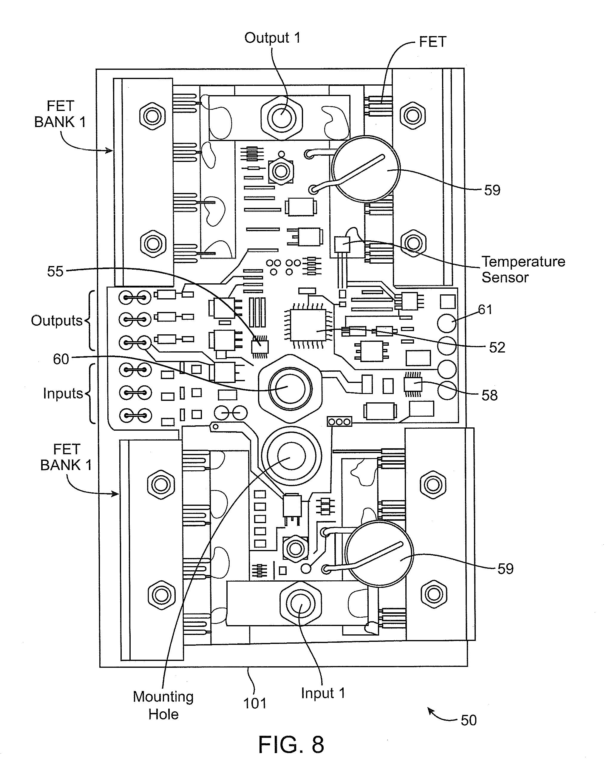
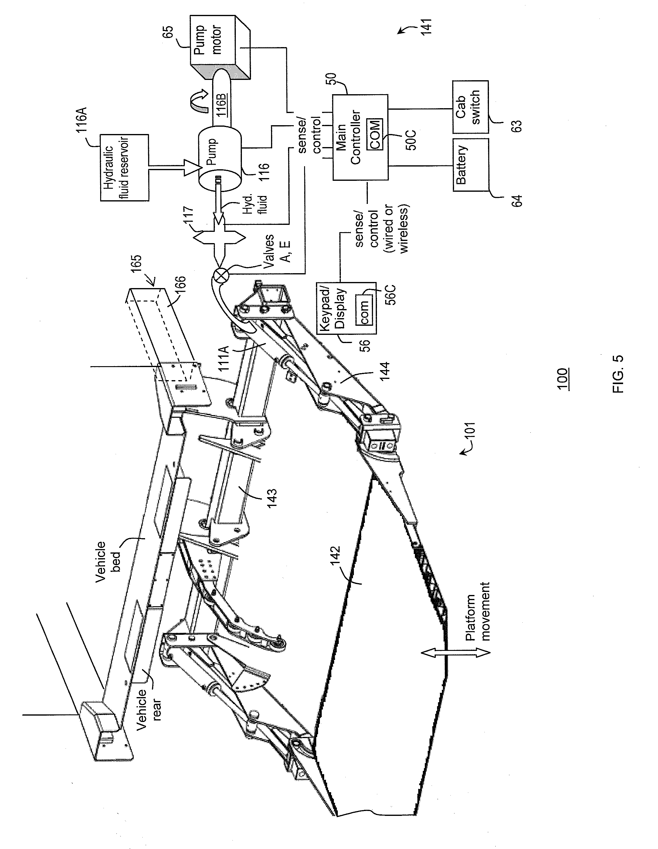
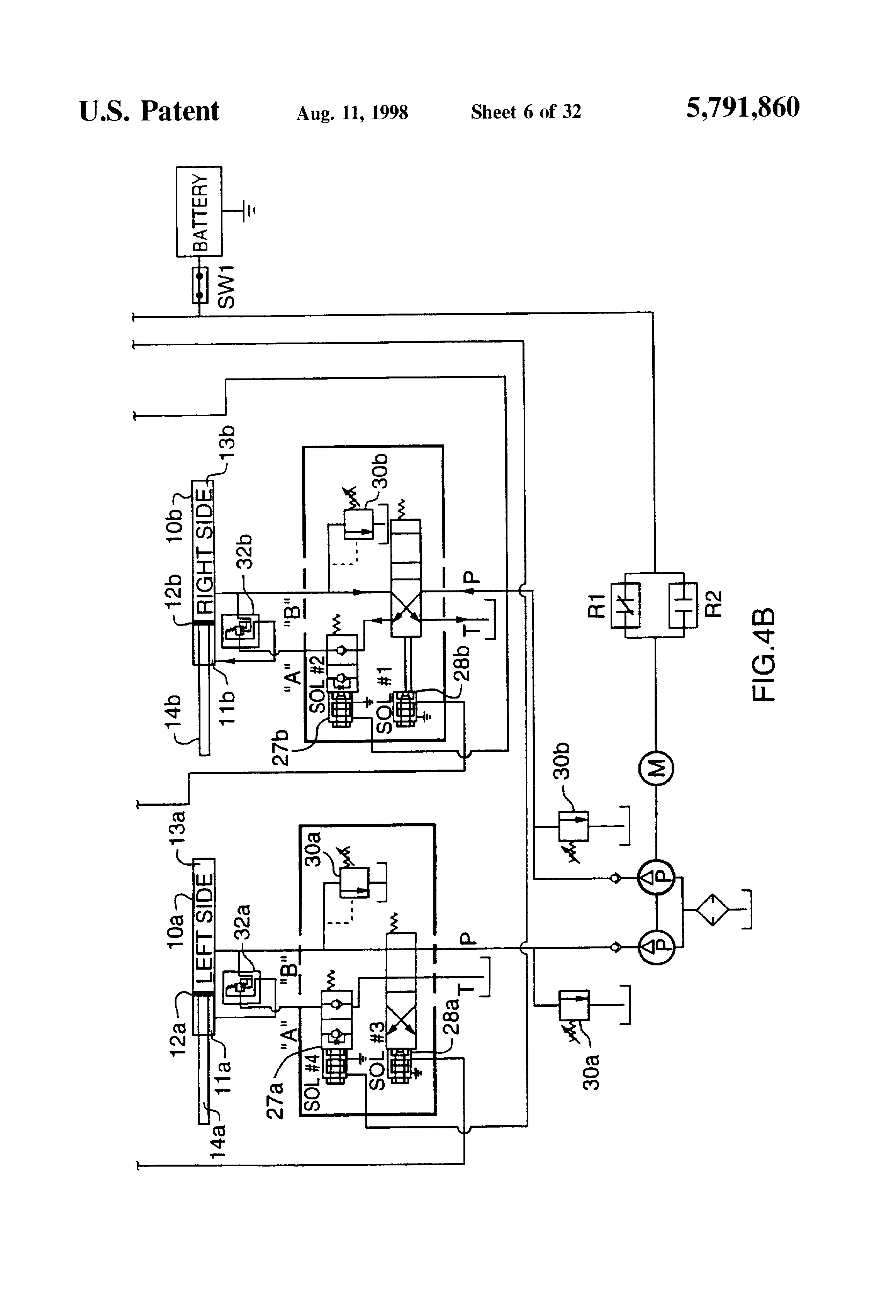
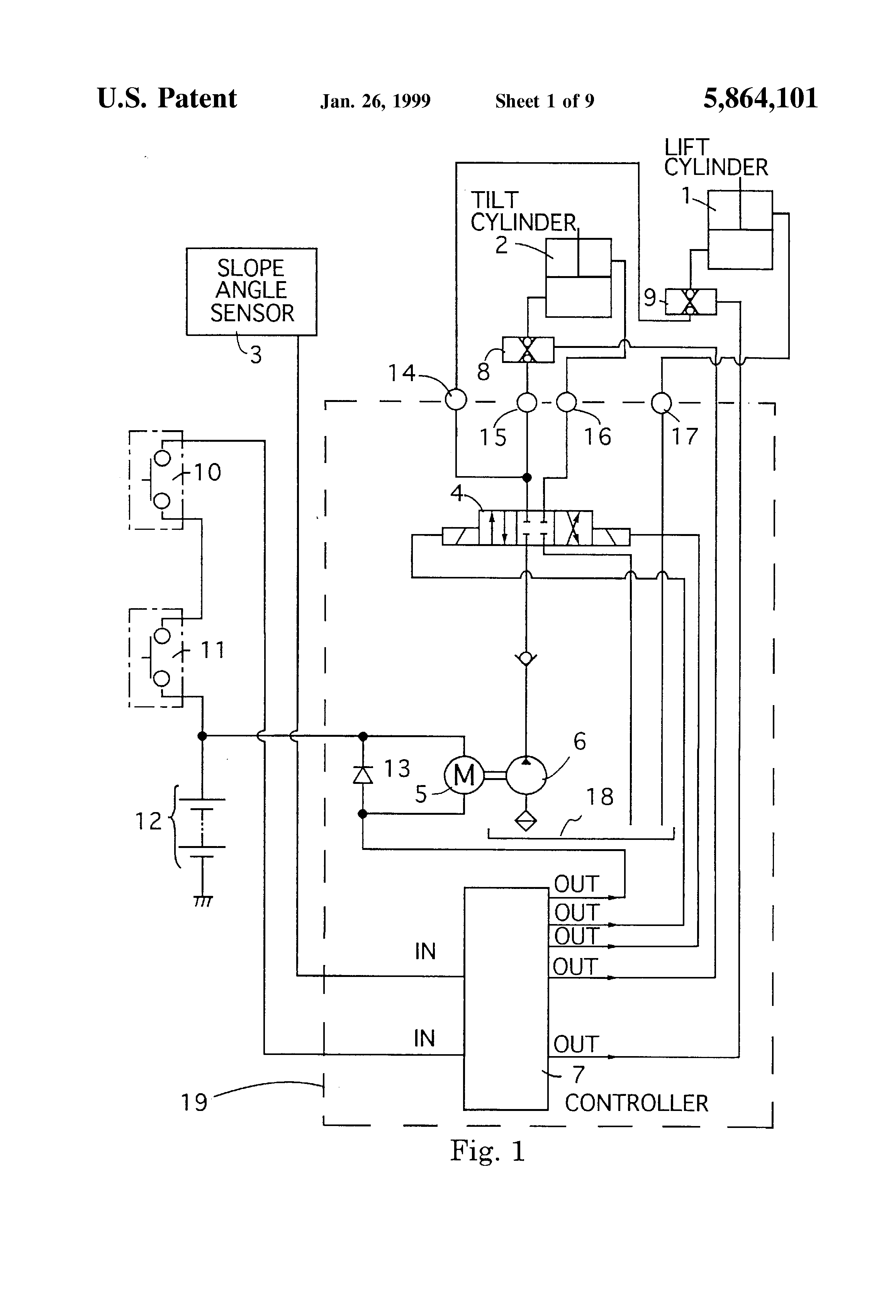
TE HYDRAULIC SYSTEM DIAGRAMS. HYDRAULIC.
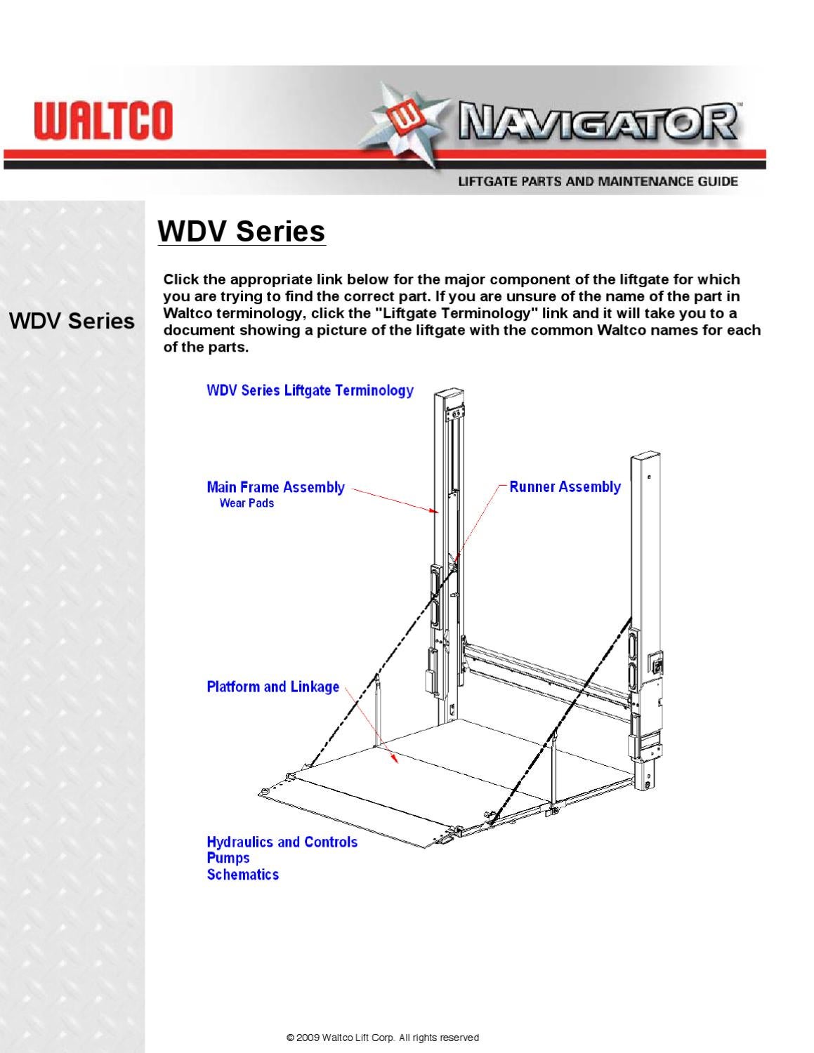
Hydraulic & Electrical System Diagrams. • Troubleshooting All Liftgates returned are subject to inspection and a 15% restocking fee. Any returned ..

Check switches, circuit breaker and wiring connections at the gate as well as inside pump. Disconnect Switch Control from Wire Harness (FIG.

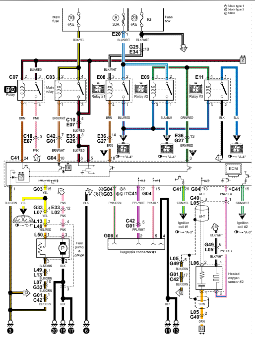
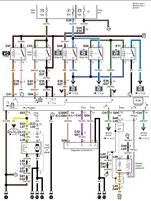
from Liftgate while installing electrical parts. Refer to GRAVITY DOWN LVTS WIRING DIAGRAM ( FIG.
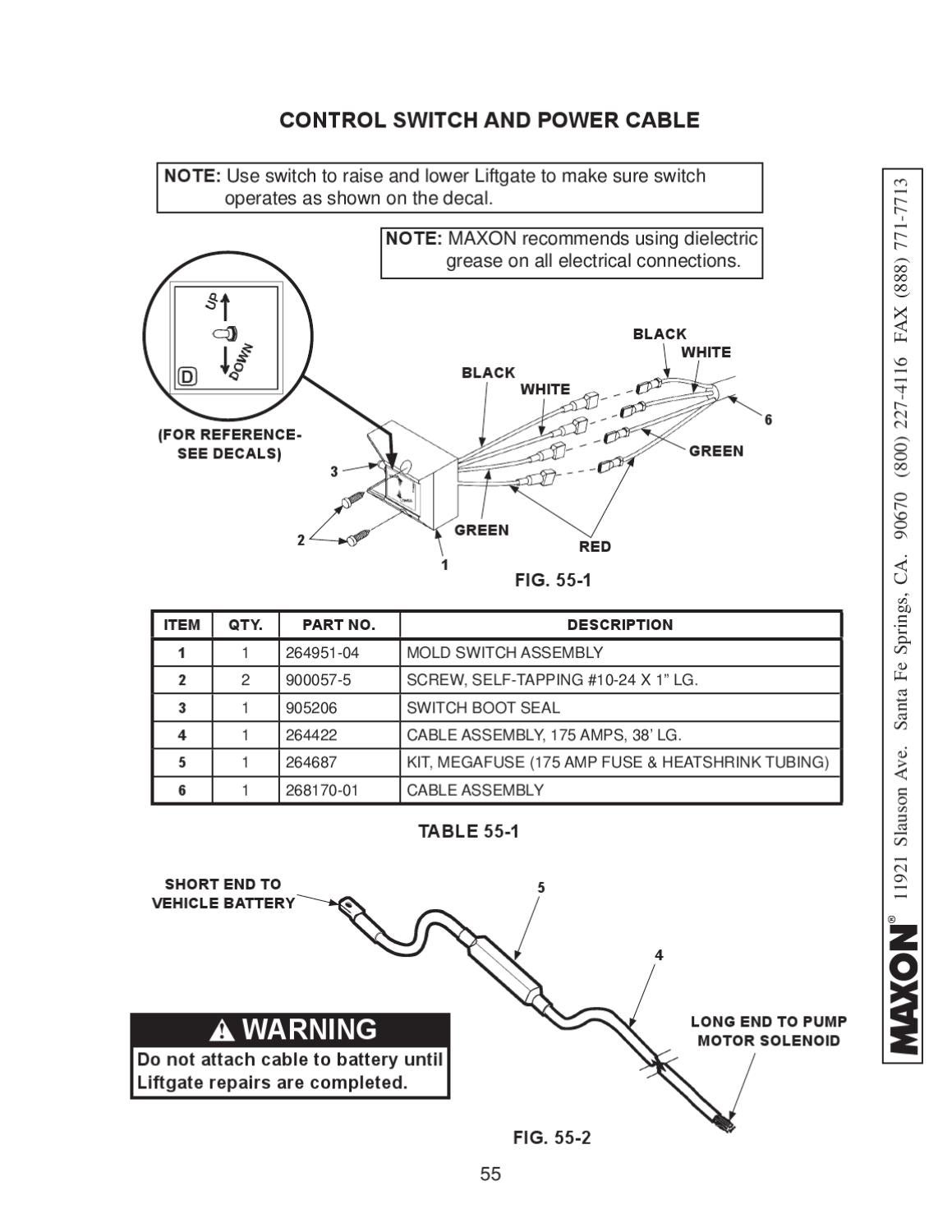
Standard Liftgates – 2 years from ship date or 6, cycles .. CONTROL SWITCH AND POWER CABLE.
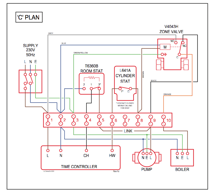
HYDRAULIC SYSTEM DIAGRAMS. .
Check electrical wiring for chafing and make sure wiring connections are tight and free of.• Read and understand the instructions in this Maintenance Manual before performing mainte-nance on the Liftgate. • Before operating the Liftgate, read and understand the operating instructions in Operation Manual.
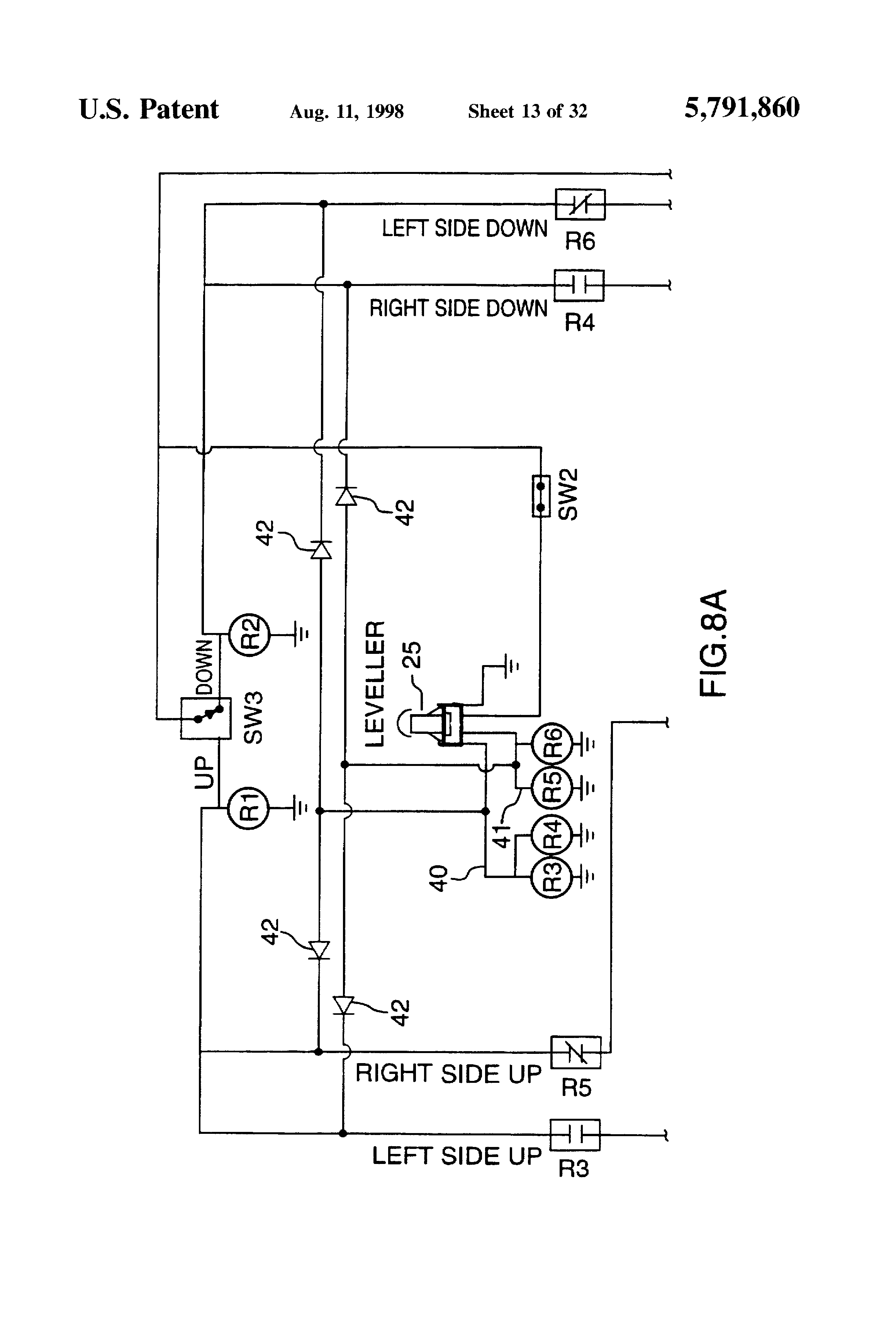
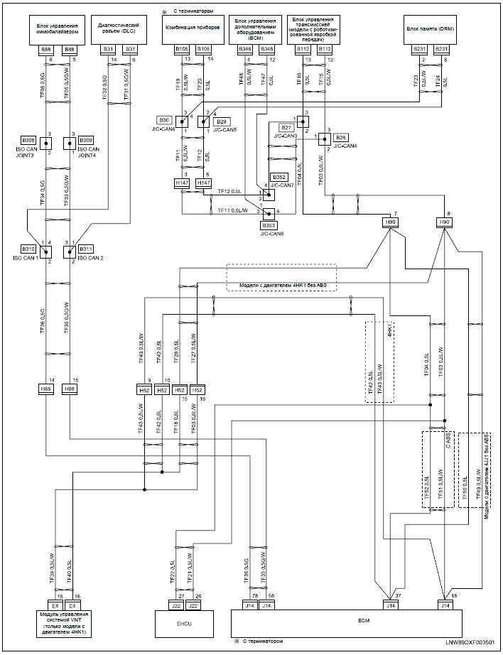
• Comply with all WARNING and instruction decals attached to the Liftgate. Maxon Liftgate Switch Wiring ~ here you are at our site, this is images about maxon liftgate switch wiring posted by Benson Fannie in Diagram category on Oct 31, You can also find other images like wiring diagram, parts diagram, replacement parts, electrical diagram, repair manuals, engine diagram, engine scheme, wiring harness, fuse box, vacuum diagram, timing belt, timing chain, brakes.
• If an emergency situation arises (vehicle or Liftgate) while operating the Liftgate, release the con-trol switch to stop the Liftgate. • Read and understand the instructions in this Installation Manual before installing Liftgate.

• Before operating the Liftgate, read and understand the operating instructions in Operation Manual. BPl 3-Terminal toggle switch BPl Box with toggle switch ready for wire and mounting BPl Box, gasket, plate, screws, strain relief (no toggle; no boot) BPl Complete box wired with sealed toggle switch ready to mount, epoxy coated, weather resistant aPl 3-Terminal toggle switch NlM 4-Wire Replacement wPl 3-Wire OE.
Heat shrink all connections. If switch cord and pump unit have plug in connectors, new switch should plug directly into existing gendered connectors on pump, regardless of wire colors.
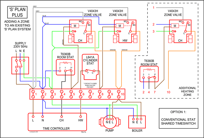
WDL inside controls. New 3-wire switch to replace 4-wire switch. These instructions assume that the existing four-wire inside harness will be reused.Maxon Wiring Diagram | Wiring LibraryWaltco Liftgate Wiring Diagram – schematron.org
