ITT McDonnell & Miller is the recipient of the highly coveted. “ISO & ” MT Control w/manual reset & test switch.
2 .9). RSLP.
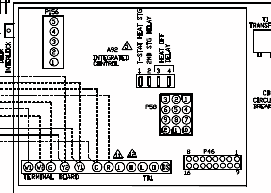
Optional features; – Low voltage switches for self-generating millivolt; circuits; – Manual reset switch; Large float chamber; Maximum steam pressure 20 psi ( is as follows: Peerless GSP-D, Mcdonnell & Miller 67 LWCO, I have been following wire Diagram 4 on the WFE install manual. Install manual fill valve and bypass line for 67 w/ volt burner circuit.
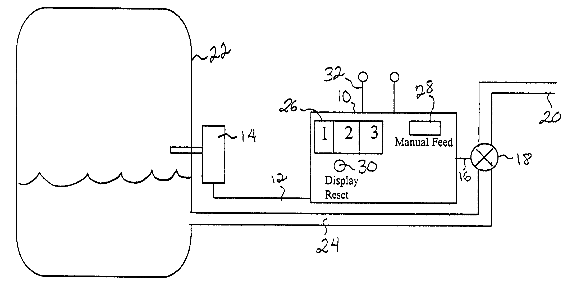
6. 4 . NOTE: McDonnell & Miller Series PS LWCO’s have a 15 second DOM (Delay on .
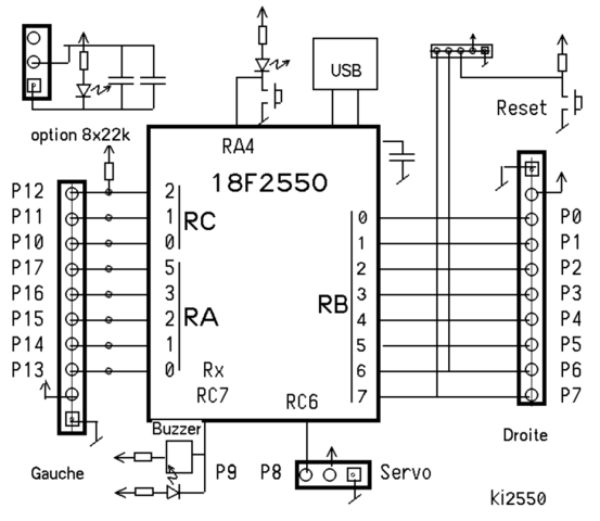
ITT McDonnell & Miller is the recipient of the highly coveted. “ISO & ” MT Control w/manual reset & test switch.
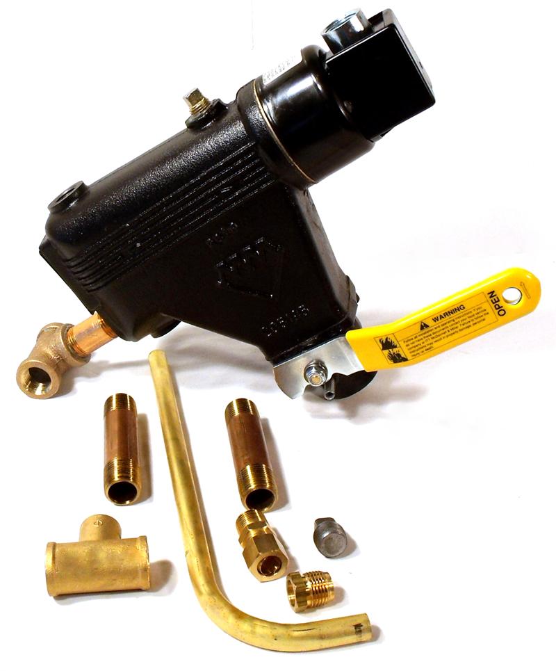
2 .9). RSLP.McDonnell Miller Series 67 Low Water Cut-Offs – Mechanical For Steam Boilers McDonnell Miller Series 67 Low Water Cut-Offs – Mechanical For Steam Boilers.
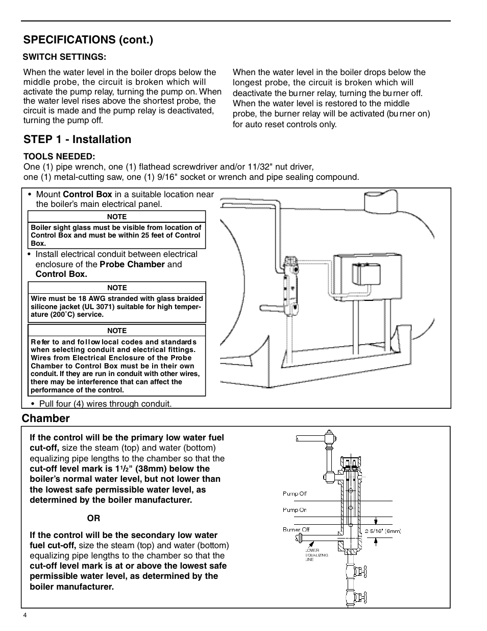
Low Water Cut-Offs – Mechanical For Steam Boilers. Series 67 • For residential and commercial applications • Lever-operated, full port ball valve for easy blow down. McDonnell & Miller.
McDonnell & Miller is a leader in engineering and manufacturing boiler controls, liquid level controls, low-water cutoffs, and flow switches for steam and hot water boilers in industrial, commercial, and building trades applications. McDonnell & Miller Chicago, IL U.S.A.
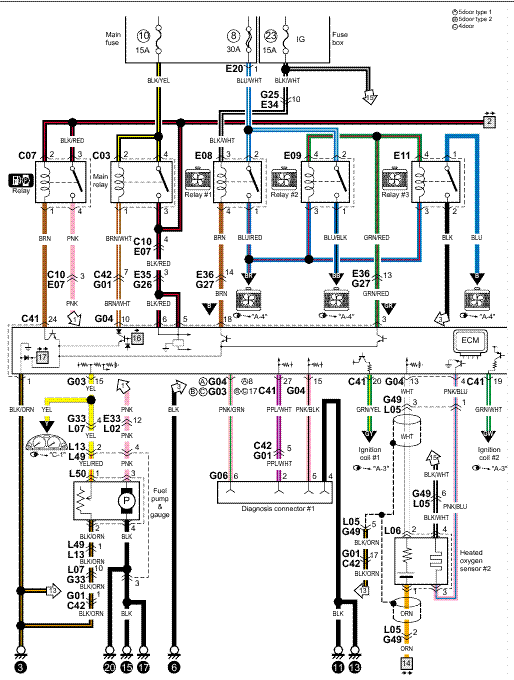
Wiring Diagram Legends 1. Bold lines indicate action to be taken in Step shown.
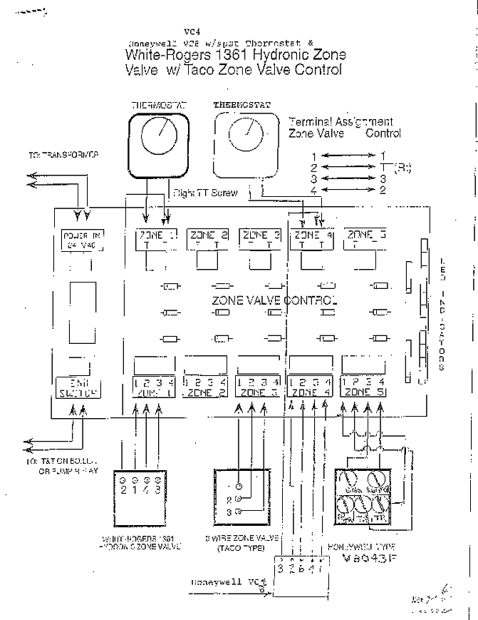
2. Grey lines indicate existing wiring.
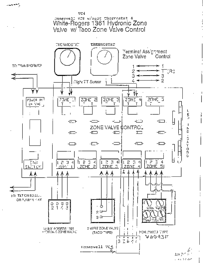
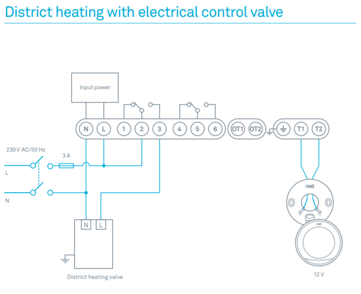
Diagram 4 WF2-U / 67 with 24 volt burner circuit WN H BURNER 12 34 NEUTRAL VAC . Mcdonnell & Miller – 67, Float Type Low Water Cut-off (Steam) – Features: For residential and commercial applications For boilers of any steaming capacity Quick hook-up fittings provided Lever-operated, full port ball valve for easy blow down Adjustable BX outlet for easy installation Dual precision switches for dependable operation of the low water cut-off and alarm or electric water.
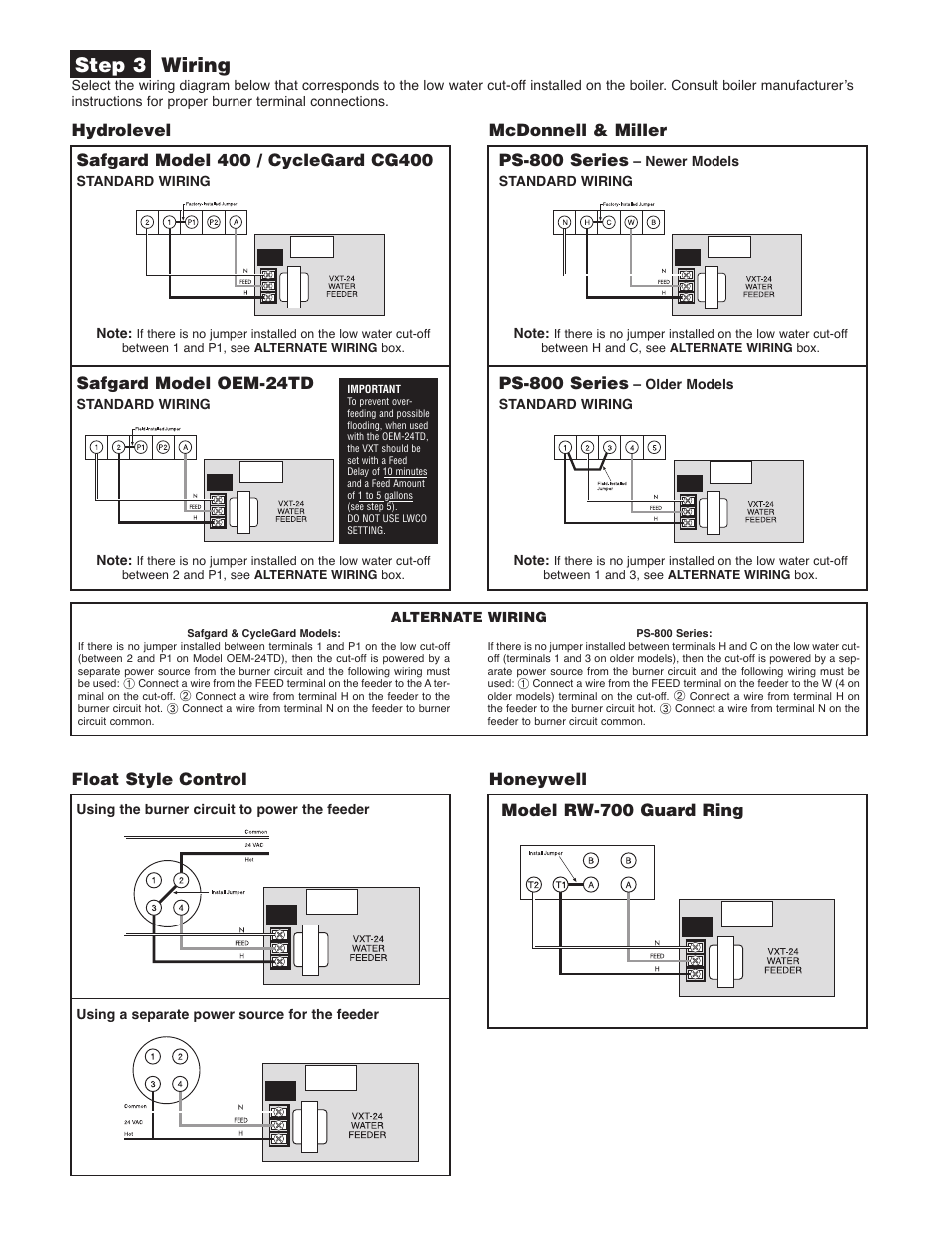
For 67 Low Water Cut-Off Installed with McDonnell & Miller Series A Water-Feeder For the V Burner/V Feeder setups. BURNER VAC SUPPLY 12 34 N H A 69 c. Using a wire nut, connect a wire from the neutral side of the power supply to one of the wires inside the feeders junction box.
(Does not make a difference which one).Series 67 – Low Water Cut-Offs – Xylem Applied Water Systems – United StatesSeries 67 – Low Water Cut-Offs – Xylem Applied Water Systems – United States