(MEFI 3 – Software).
L . You should be familiar with wiring diagrams, the meaning of engine wiring harness, and is a pin connector, which is. This article covers the fourth-generation of the GM MEFI system, known as It has two connectors and three mounting bosses.
. Here is the wiring diagram.
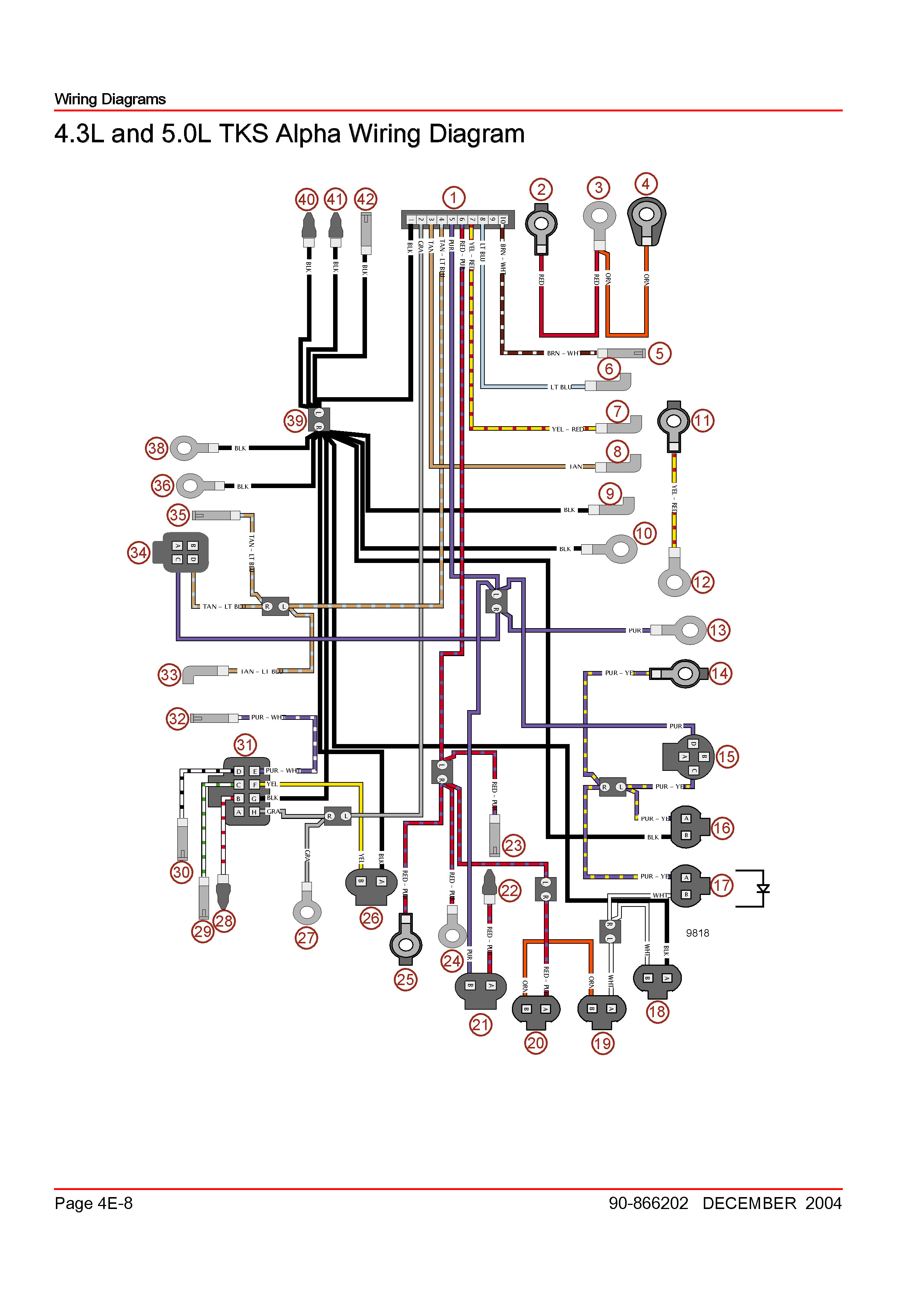
This article covers the fourth-generation of the GM MEFI system, known as It has two connectors and three mounting bosses. . Here is the wiring diagram.
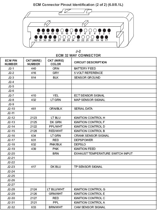
Section 8 – ECM Wiring. 8 – 3.
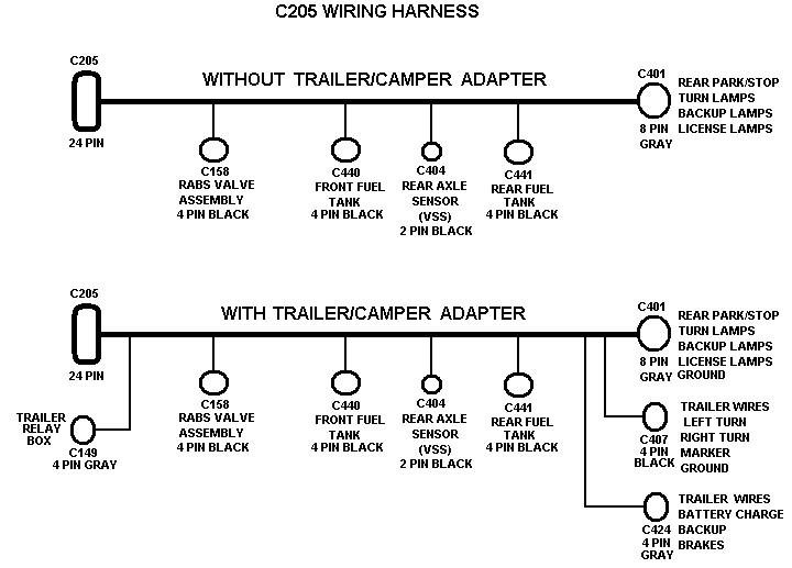
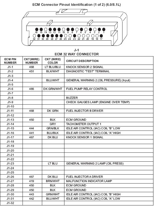
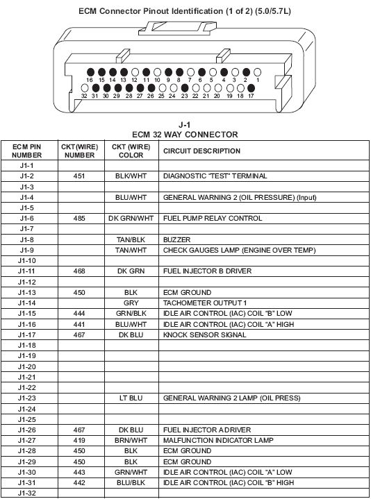
Marine. MEFI 1 ECM Connector Identification (2 of 2). J ECM 32 WAY OUTPUT CONNECTOR.
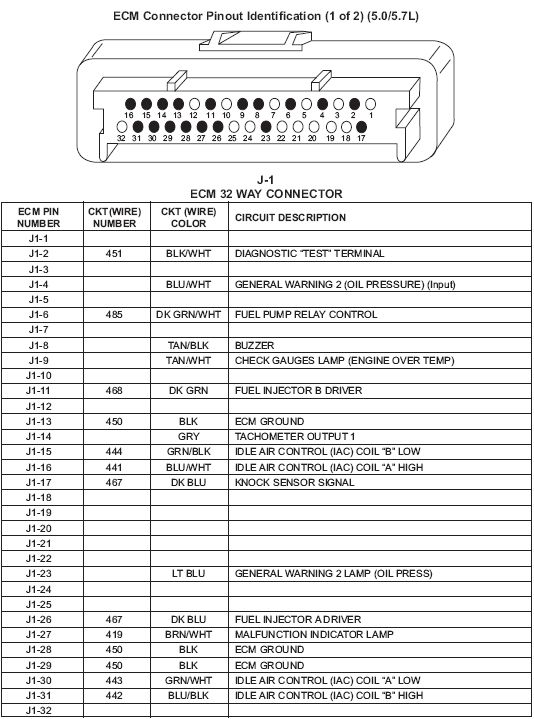
ECM PIN. CKT(WIRE).
The wiring schematics and circuit identifications are for the GM MEFI originally . 5 – 3.
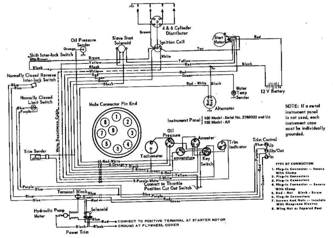
Marine. ECM Wiring (2 of 5). Engine Control Module (ECM).The MEFI 6 Scan kit includes: A MEFI 6 Scan Electronics Interface A 6-foot USB Cable to connect the Electronics unit with your laptop or PC A foot Vehicle Interface Cable that goes between the electronics box and the vehicle.
A CD with the MEFI 6 Scan software SHIPPING NOW! The Shift Switch shown in the wiring diagram is used on Alpha models only. The switch is V6 AND V8 / CID ENGINES WITH MEFI-3 Page 6 of 6 JULY V6 ( cid) and V8 (/ cid) MEFI 3 PAGE 3 OF 3 AUDIO WARNING CIRCUIT TO TACH TO .
Apr 04, · Here are pictures of the back of a Mercruiser MEFI-3 ECM: (DELPHI with barcode KA) The side of this ECM has a F02D marked on it; this is the calibration checksum for this ECU in Hex. Further note that the confirms this is a MEFI-3 ECM by the Rinda connections documents, schematron.org and the OBD2AllInOne site.
Apr 13, · Hi, I am in need of a mefi 1 mercruiser v8 wiring diagram. I have the mefi 1 with harness and the mefi burn software.
truck pulling,, small 5/5. 2 IGNITION COIL WIRING CONNECTOR Pin A is B+ from MEFI System Relay Pin B is unused Pin C connects the Ignition Coil to the Ignition Module 3 HEAT SINK 4 IGNITION CONTROL MODULE MOUNTING SCREW 5 IGNITION CONTROL MODULE WIRING CONNECTOR Pin A is B+ from MEFI System Relay Pin B connects to ECM Pin JCBM Motorsports MEFI 4 Electronic Control Modual Technical InformationOBD Diagnostics
