6 – 0 Power Trim. Trim System Wiring Diagrams.
6 – 10 Power Trim Hydraulic Schematic. 6 – 13 ..
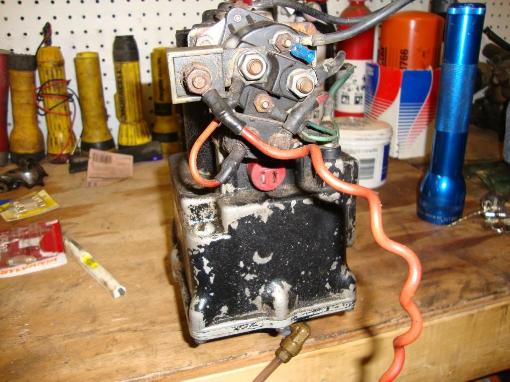
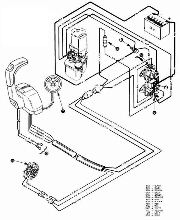
c – “UP” Solenoid d – Amp Fuse. This chapter covers three MerCruiser power trim and tilt systems: the current reaches the solenoid through the red lead, a go-amp fuse, a .
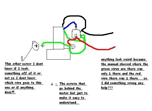
Reconnect wires to back of new switch/sender. .
Figure 2 is a functional diagram of the hydraulic. I need some help wiring my Harbor craft deck boat trim and limit Thanks for the schematic.
The BLUE & GREEN wires bring 12 volts fromthe toggle trim/ tilt and trailer switches to the two solenoids on the pumpassy. Find the cheap Mercruiser Trim Solenoid Wiring Diagram, Find the best Mercruiser Power Trim Hose (Port Side) for the R, MR, Alpha One and Alpha One Gen.
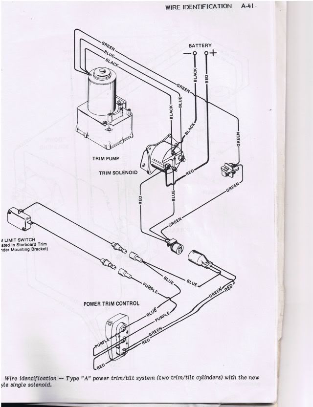
Mercruiser Power Trim System Wiring Diagram at Performance product Technologies/schematron.orgThe best source for Mercruiser OEM parts, marine engines, boat & engine parts, accessories, boating supplies, tools, & aquatic sporting goods. Top Rated Plus.
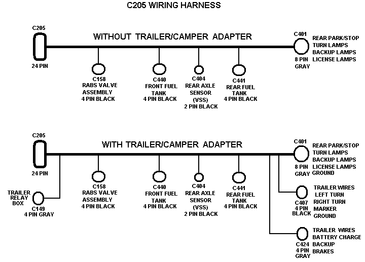
Sellers with highest buyer ratings; Returns, money back; Ships in a We Have Everything · Make Money When You Sell · Huge Savings · World’s Largest SelectionCategories: eBay Motors, Other Outboard Engines & Components and more. Mercruiser Trim Solenoid Diagram ~ you are welcome to our site, this is images about mercruiser trim solenoid diagram posted by Brenda Botha in Mercruiser category on Nov 29, You can also find other images like wiring diagram, parts diagram, replacement parts, electrical diagram, repair manuals, engine diagram, engine scheme, wiring. Power Trim and Tilt Systems The MerCruiser power trim system permits Single Solenoid System A 3-button power trim panel control operates the single solenoid system shown in Figure 1.
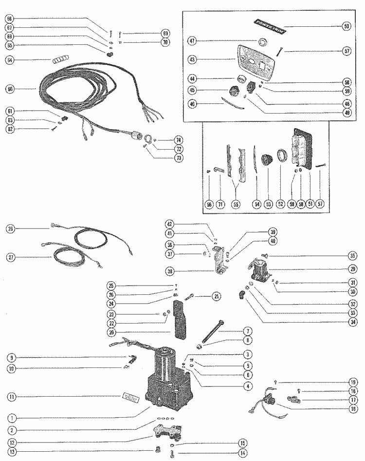
to the blue/white wire and on to the solenoid to drive the unit to its full up position. WIRING DIAGRAMS – 4D-1 Wiring Colors for MerCruiser BIA Color Code Where Used Black All Grounds Brown Reference Electrode-MerCathode Orange Anode Electrode-MerCathode Lt.
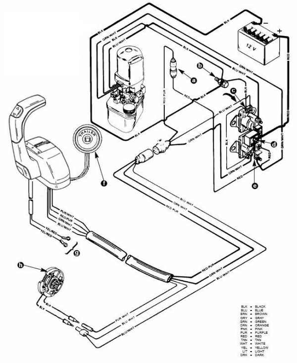
Blue/White Trim- ”Up” Switch Gray Tachometer Signal Green/White Trim -”Down” Switch Tan Water Temperature Sender to Gauge Lt. Blue Oil Pressure Sender.Mercruiser tilt/trim wiring – schematron.orgMercruiser Power Trim Wiring Schematic | schematron.org
