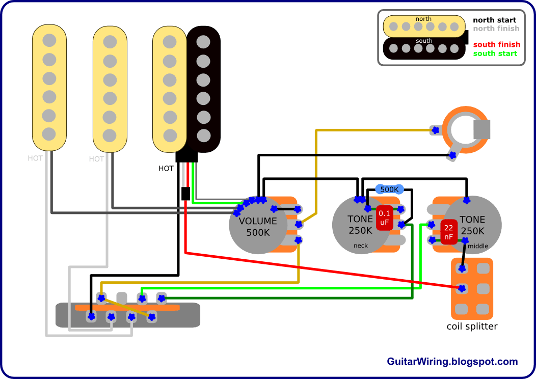
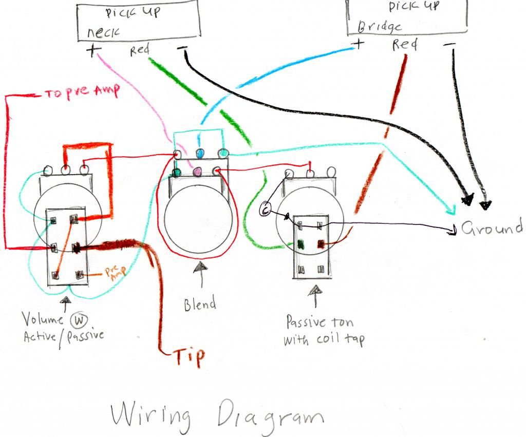
View instructions with Adobe Acrobat Reader or higher. Download Adobe Acrobat free from Adobe. Mighty Mite MMFR-4 Bass Humbucker Wiring Diagram.
also learned how to use the amp’s tremolo circuit too to add another dimension to .. ” was, according to the chart, used in tweed Pros up until the brown.
Mightymite says: red & blue together, black = hot, white & bare = ground on their You should be able to figure out which schematic is correct. View instructions with Adobe Acrobat Reader or higher. Download Adobe Acrobat free from Adobe.
Mighty Mite MMFR-4 Bass Humbucker Wiring Diagram. BuGGFX Handmade Mosfet Marshall JTM45 Emulator.
50% price drop The wiring is probably not correct for the model (see Whole Story). • The truss-rod.The mighty mite website had a diagram without instructions.
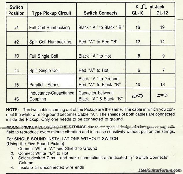
I found a post on line which I tried to confirm with a multimeter and could not, but turned out these instructions were perfect. 22ohm pickup; solder red and blue together, tape off.
Find great deals on eBay for mighty mite switch. Shop with confidence.
Find great deals on eBay for mighty mite bass pickups. Shop with confidence. Nov 22, · I think that is great!
and I believe it is correct. You have one pole on each switch to do the basic tone changing, and the others work together to stop the disconnected coil hanging off . Dec 17, · I bought a 3-way tele switch from schematron.org, and it isn’t like the typical fender switch.
the mighty mite switch is rectangular and all of the posts are in a straight line on one side of the switch (not staggered).The Marketplace for Musicians | schematron.orgmighty mite 3 way switch wiring | Telecaster Guitar Forum