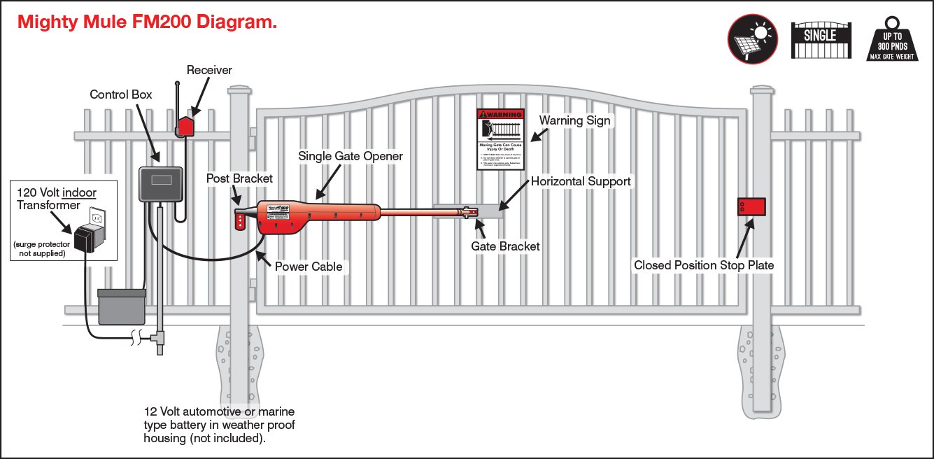
Connecting Light Kit to Mighty Mule and GTO/PRO-SW Openers .

schematron.org 8 . Figure 15 and the Wiring Diagrams on the following pages. 1.
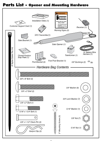
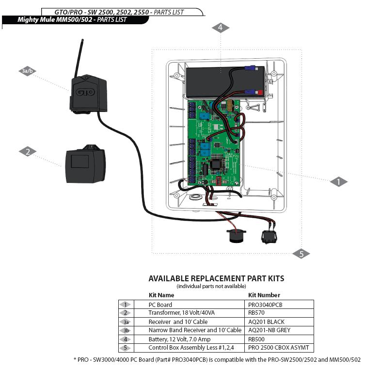
Important: detailed wire routing diagrams – Mighty Mule FM User Manual. Page 24 The wires from the battery harness, receiver, transformer or solar panel. The Mighty Mule Gate Opener is intended for use with vehicular swing gates in The diagram shown below is an example of a pull-to-open installation on a.

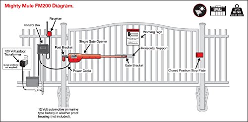
The Mighty Mule® E-Z Gate Opener is designed for installation on a . Pay close attention to the diagram below and be aware of these areas at all times. .. on use with a transformer and one(1) 12 Volt battery.
lbs. lbs.

lbs. © GTO, Inc.
For use with all GTO Access Systems and Mighty Mule AC and DC powered gate operators. Receiver.
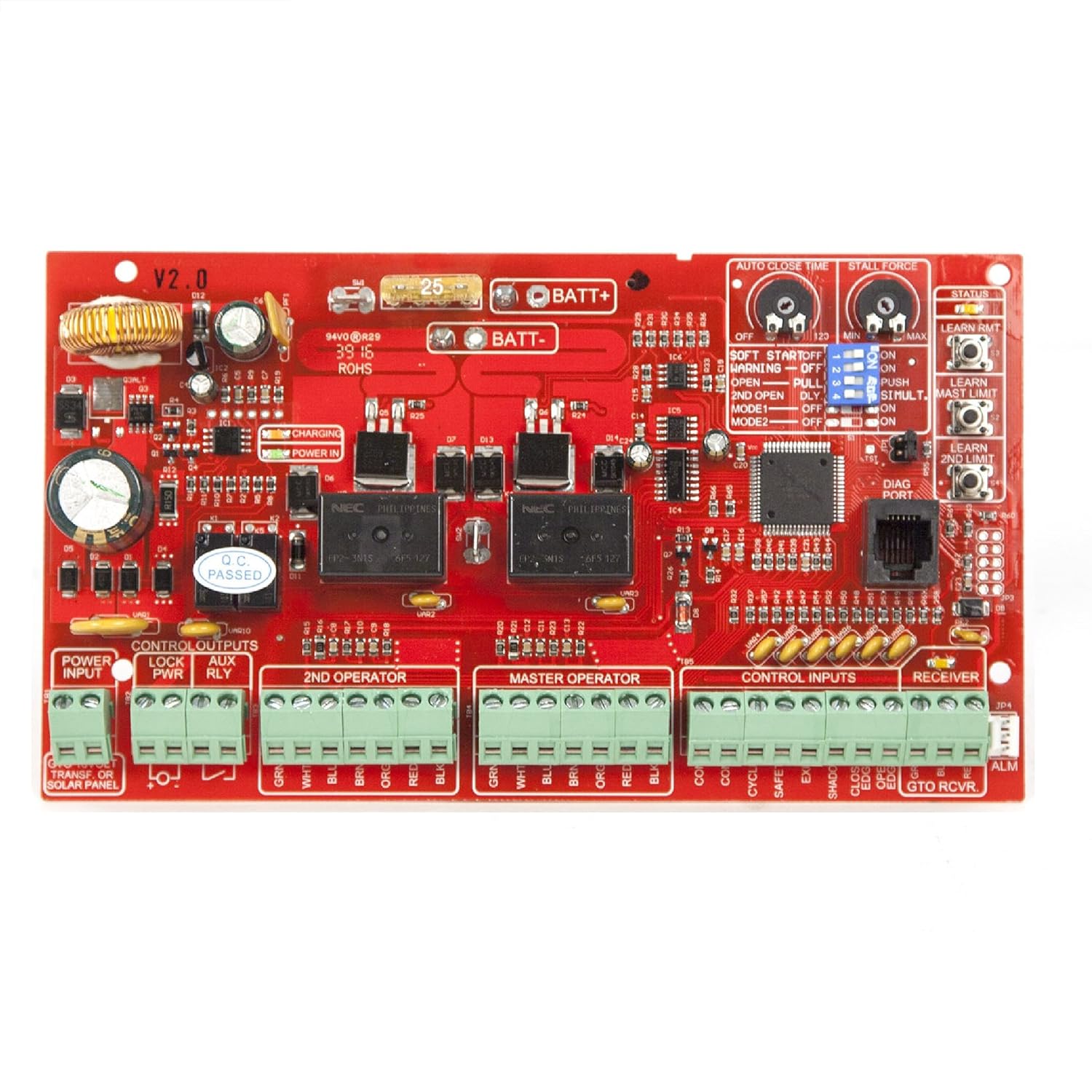
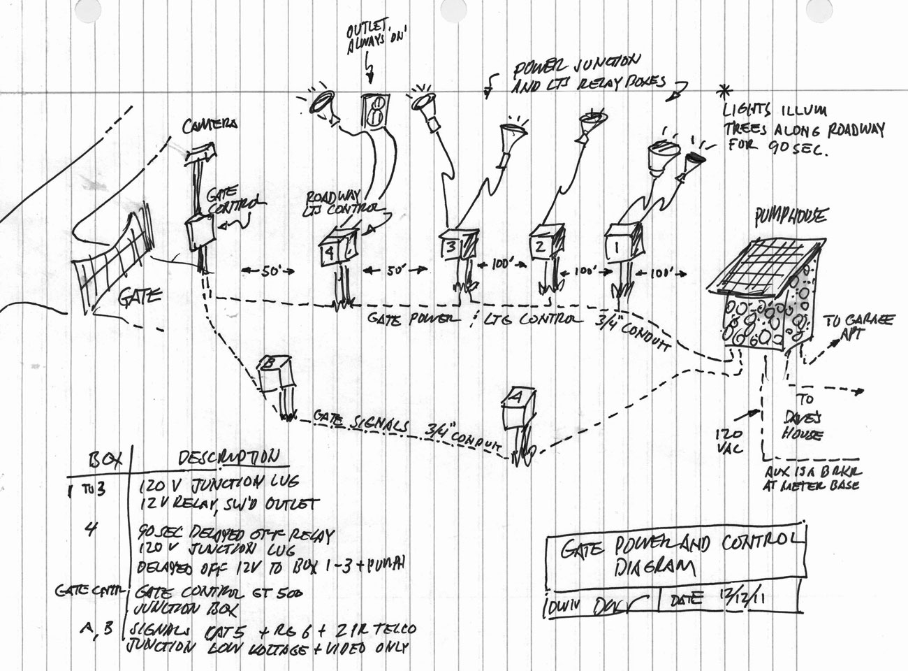
Diagram illustrates correct placement of photo beams in relation to the gate. Connecting wires to the terminals ( normally open wiring).
Connecting Mighty Mule. FM Gate Opener Control Board.Search Results for mighty mule at Tractor Supply Co.
Mighty Mule Photo Eyes for Mighty Mule Gate Openers SKU # Product Rating is 0 (0) Free Delivery Offer! Click here for more details.

Standard Delivery. Free Delivery Offer!

Click here for more details. Installation Manual for the WARNING!
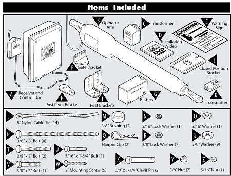
Detailed Wire Routing Diagram page 20 Connecting the Transformerpage 21 The Mighty Mule® E-Z Gate Opener is designed for installation on a pull-to-open single leaf gate (gates that open into the property). The other end of the single length of wire is connected to the COMMON terminal on the Mighty Mule control board.

Connect the RED wire from the sensor to the AUX OUT (H) terminal, and the BLUE wire to the EXIT terminal on the Mighty Mule control board. Battery/Power Cable Harness / Part# R Battery/Power Cable Harness / The R is the battery/power cable for the / and it is . Download installation manuals for your Mighty Mule products.Detailed Wire Routing Diagram – Mighty Mule Installation Manual [Page 24]Mighty Mule Manuals
