Mule Installation Manual for information on these adjustments. Installing the lock with a GTO/PRO gate opener may require slight movement of. The Mighty Mule® Gate Opener is intended for use with vehicular swing gates.
The opener . buttons, automatic gate locks, and other access control products. To wire or connect the Automatic Gate Lock to a Mighty Mule /, PRO /,.
PRO , or a PRO , follow these instructions: 1) Locate the Lock. Mule Installation Manual for information on these adjustments. Installing the lock with a GTO/PRO gate opener may require slight movement of.
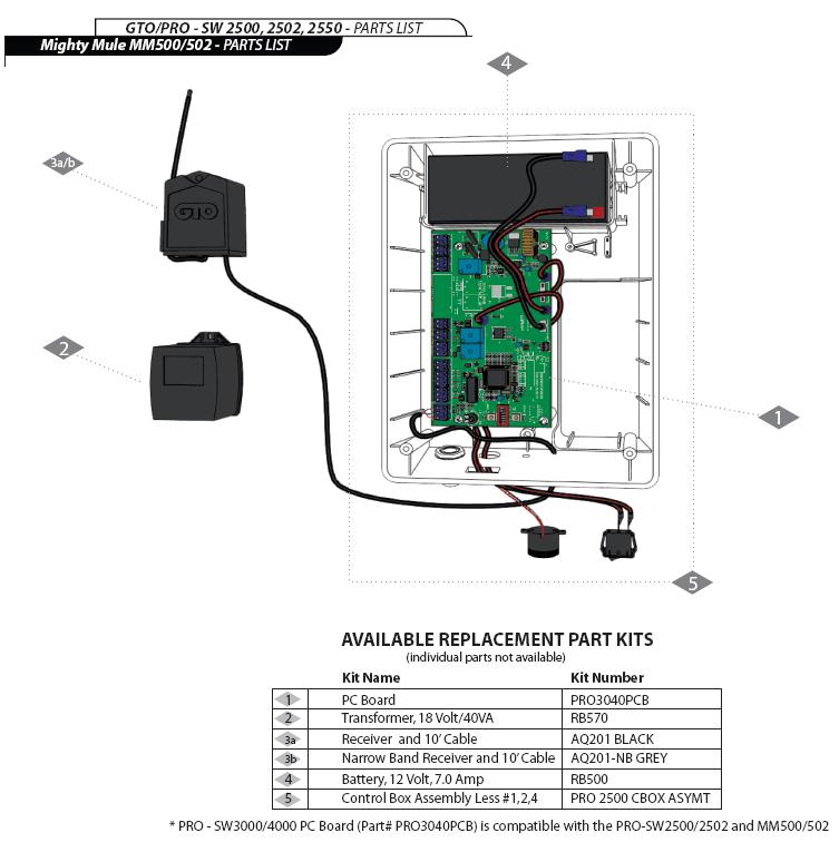
To wire or connect the Automatic Gate Lock to a Mighty Mule /, PRO /,. PRO , or a PRO , follow these instructions: 1) Locate the Lock.Award Winning Technical Service Team. GTO Access Systems, LLC, the designer and manufacturer of the Mighty Mule, GTO/PRO,and GTO Access Systems brands of gate operators and access controls has been the leader in the access control industry for over 23 years.
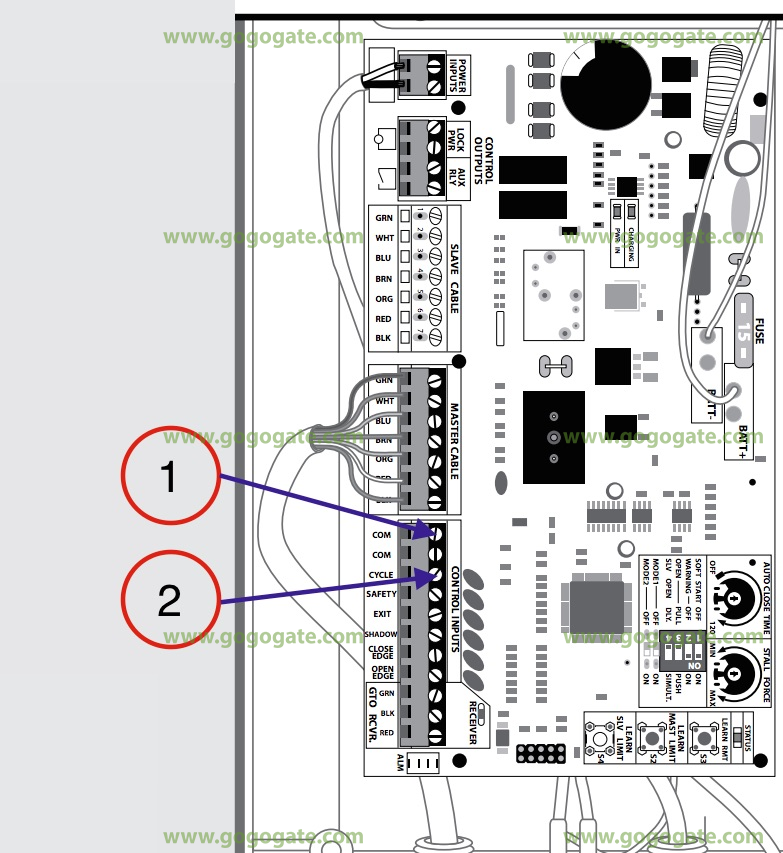
wiring diagram for mighty mule need to know wiring diagram for green white red black and blue – GTO Mighty Mule FM Single question Wiring diagram for mighty mule Mighty Mule motor repair. Try schematron.org part # P6KE16CA 36 cents a piece. Posted on Jul 09, Mighty Mule Installation Manual.

Single gate opener. Gate Opener Mighty Mule UL SERIES Installation Manual. E-z gate opener (43 pages) The diagram shown below is an example of a pull-to-open installation on a chain link fence and single gate.
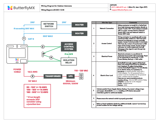
Mounting the opener on a masonry column requires special procedures; see Column. Lock Wiring to Use the following instructions to wire the Automatic Gate Lock to your gate opener. To wire or connect the Automatic Gate Lock to a Mighty Mule /, PRO /, PRO , or a PRO , follow these instructions: 1) Locate the Lock Control Board for the Automatic Gate Lock.
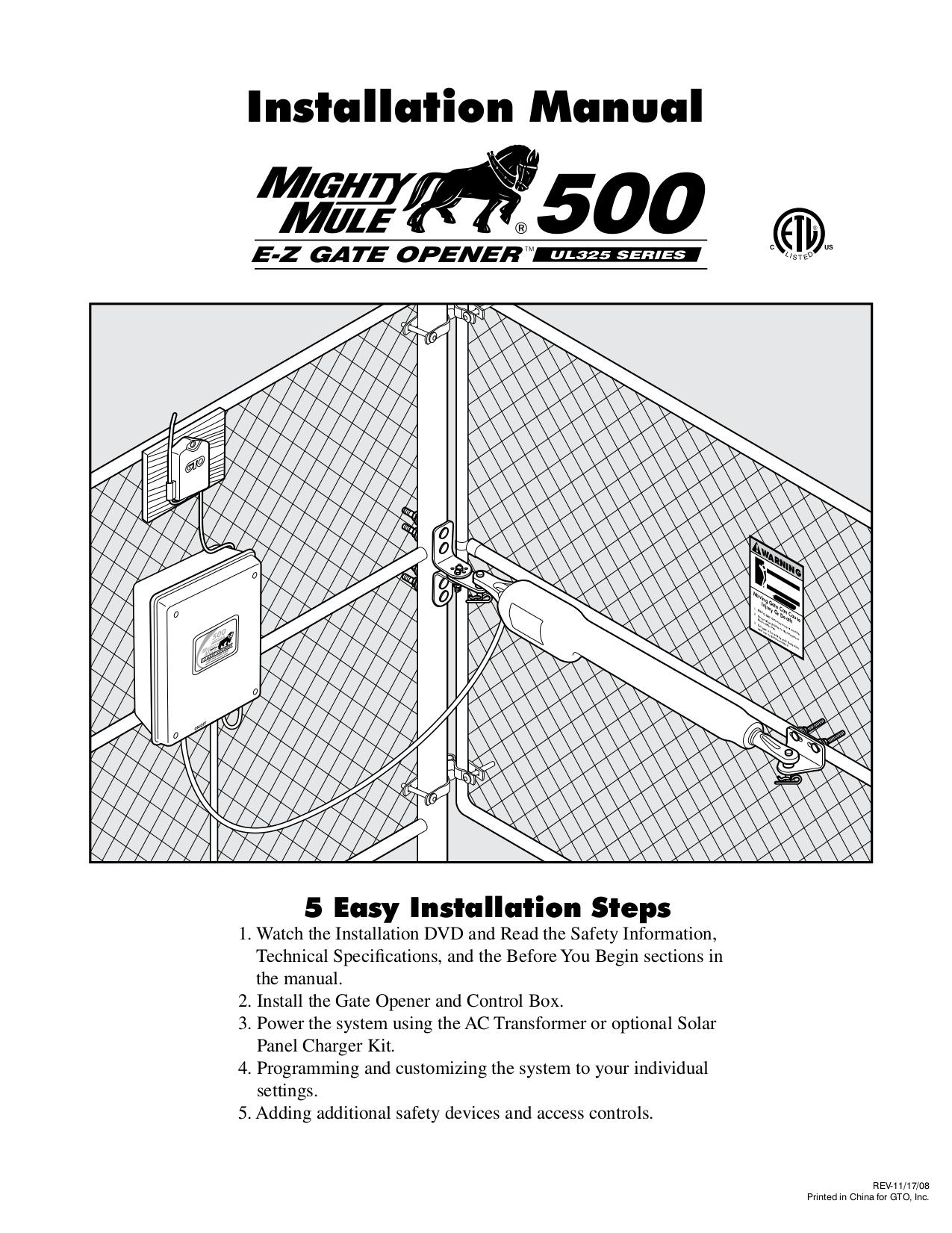
It is 1 5/16” x 2 3/16” in size. Mighty Mule UL SERIES Installation Manual. E-z gate opener.
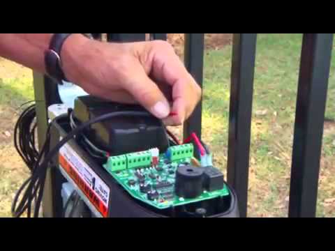
The Mighty Mule® will ONLY accept accessory devices with normally open dry contact output. Pin Lock (FM) The Pin Lock substitutes for the clevis pin at the front end of the Mighty Mule® gate openers. Helps prevent theft of the operator from the gate, while.Gates That Open (GTO) Support Center – Trouble Shooter WizardMighty Mule FM Green Board : Manual
