Gas Products.

NOVA SIT Millivolt reading for thermocouple Pilot On: 8 to 30 mv . Set meter to MV thermocouple & wires from the valve.
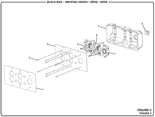
check connections. Electrical (V and millivolt) components and wearable parts such as blowers, gas valves, thermal switch, switches, wiring, remote controls, ignitor, gasketing. FLEXIBLE GAS CONNECTIONS & QUICK.
DISCONNECT The millivolt valve is a thermopile self-powered combination gas control. Before checking the.
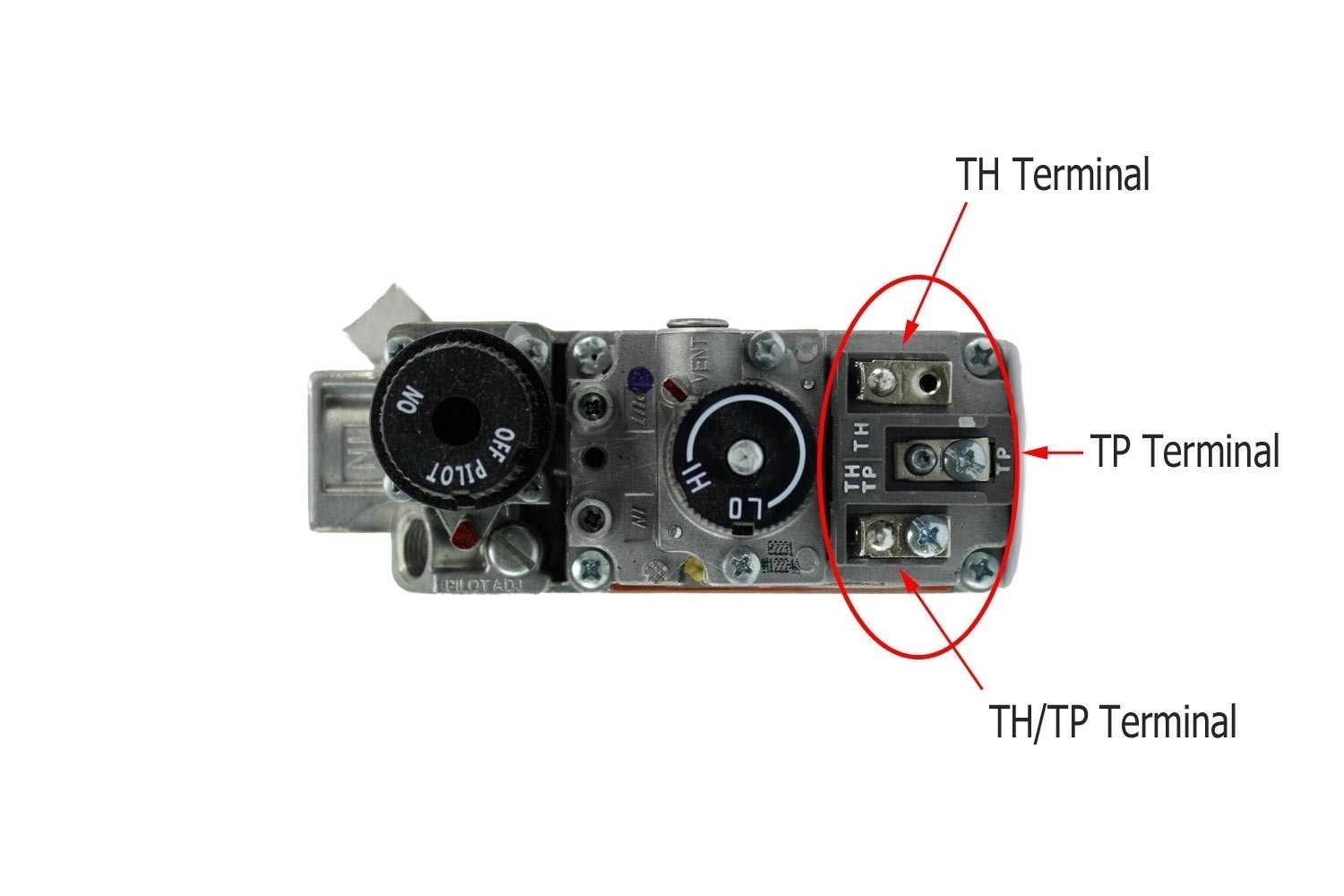
A Guide to the Different Types of Millivolt Valve Remote Controls: Fireplace remote controls provide a wonderful convenience for a gas fireplace and with the Wiring Diagram in your fireplace Installation & Operation manual. The VS, VS Millivolt Gas Valves are compact and have a .
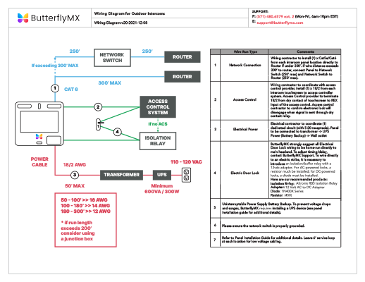
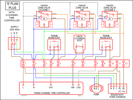
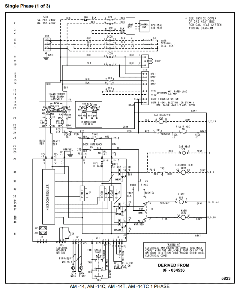
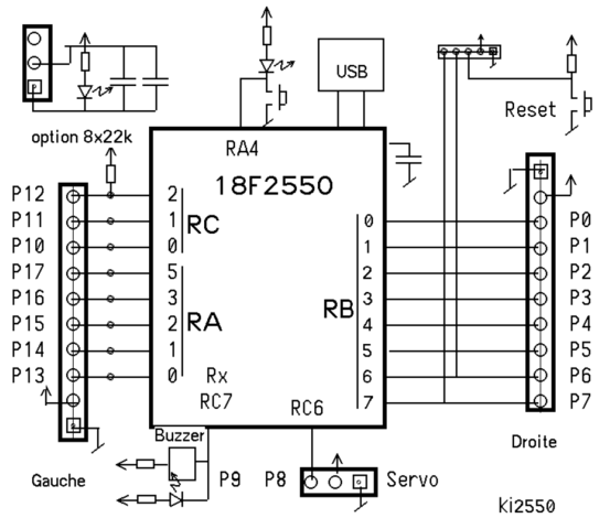
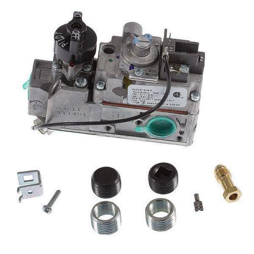
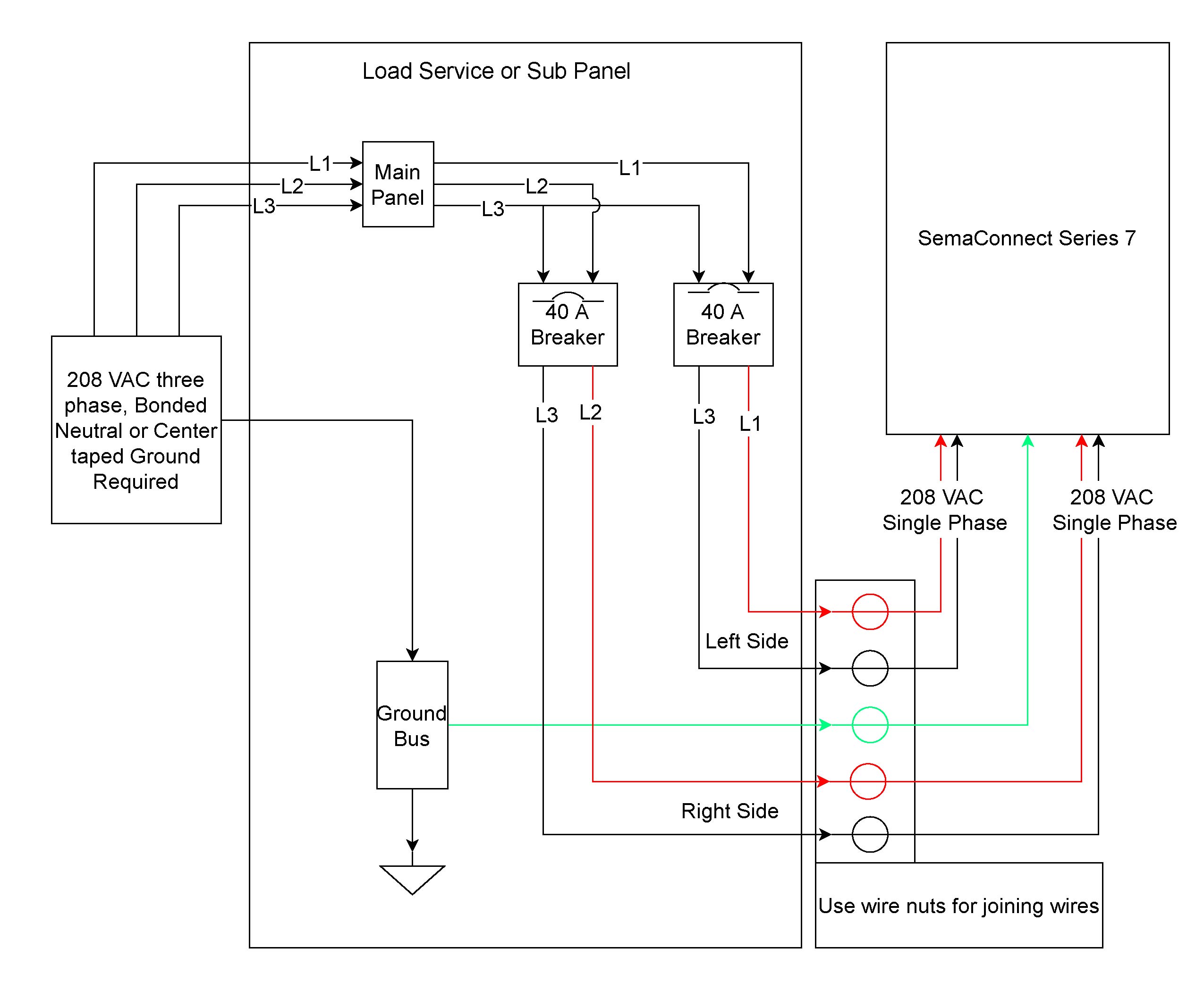
a gas valve, thermopile, millivolt thermostat, and a pilot Millivolt system wiring diagram.DEAN MILLIVOLT GAS FRYERS (NON-CE) CHAPTER 3: INSTALLATION INSTRUCTIONS Gas Conversion Procedures See gas valve illustration below and gas valve, burner and orifice location on page when performing the following conversions. Knowledge about robertshaw gas valve wiring diagram has been uploaded by Benson Fannie and tagged in this category.

Occasionally, we may have to slightly alter the design, color, or even accessories. We need a new concept for it and one of these is this robertshaw gas valve wiring diagram. VS MILLIVOLT GAS VALVE.
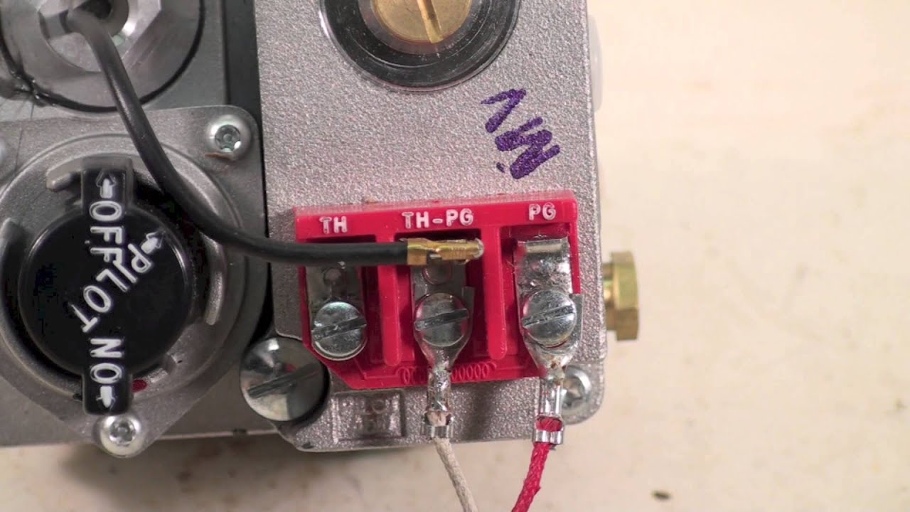
Š3 4. Disconnect power supply before making wiring connections to prevent electrical shock or equipment damage. schematron.org the power supply rating on the gas valve.
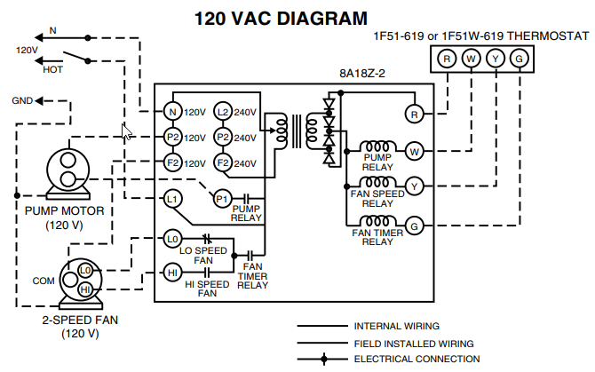
C and make sure it matches the available supply. Install the transformer, thermostat, and other con – trols, as required.
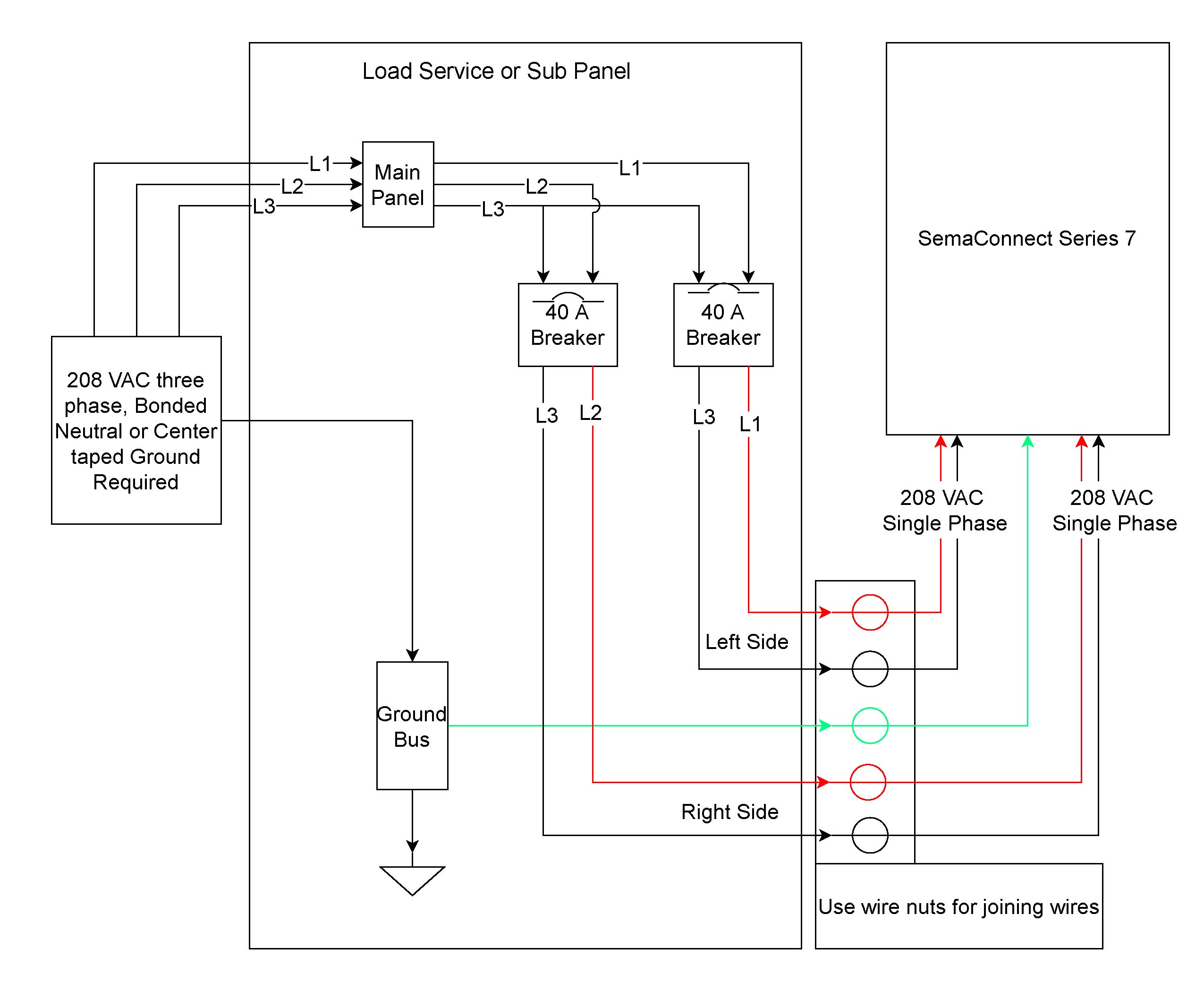
for the gas control valve. Refer to the wiring diagram on page xx for connecting the wires to the blower.
NOTE: If any of the original wire supplied must be replaced, use type 18 AWG deg. C (25 ft.

length maximum) or equivalent. MANTEL CLEARANCE TOP VIEW OF FIREPLACE BOTTOM LOUVER GAS CONTROL VALVE.
1. Disconnect the fryer from the gas and electrical power supplies.
2. Disconnect the pilot generator and operating thermostat wiring from the valve. 3.
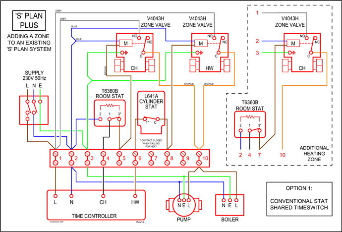
Disconnect the pilot gas tube from the valve 4. Disconnect the valve from the gas manifold and the burner assembly. 5.
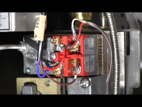
Install the replacement valve by reversing Steps 3 and 4. 6.Millivolt Pool Heater Troubleshooting GuideRobertshaw Gas Valve Wiring Diagram – schematron.org
