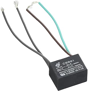
HQRP 2-Pack Ceiling Fan Capacitor CBB61 uf+6uf+6uf 5-Wire . Quest LED 5/6″ Inch Slim Disk Light 4 Pack Dimmable; Works with · $$ STM32F3xx/F4xx ARM® Cortex®-M4 programming manual (PM) .. RM 5/ DocID Rev 7. 9.
Reset and clock control (RCC). . Page 6 MP4. CO.
MP6. OP. AMP1.
(2). OP. AM.

P2. TIM1.
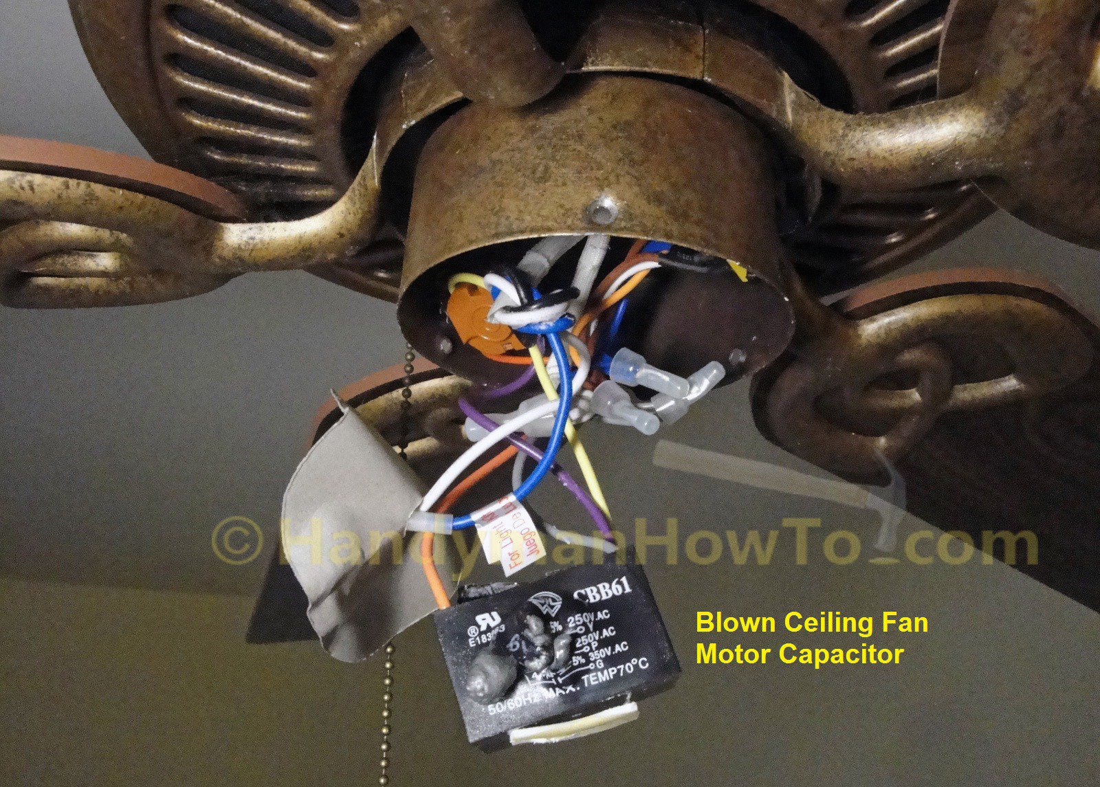
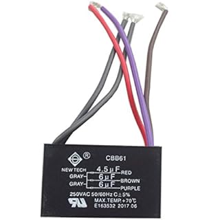
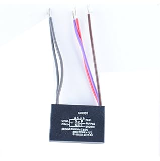
TIM TIM TIM17 All memory bytes are read (NBL[] are driven low during read transaction) and. Ceiling fan capacitors may have 2 to 5 wires.
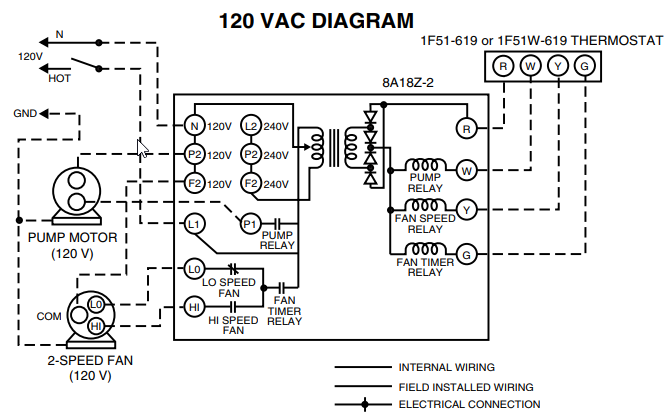
document is based on my experience fixing a ceiling fan with a 3-speed (plus off) switch and a 5-wire capacitor. The diagram below shows the sequence of switch positions.
User manual. Discovery kit for STM32F/ lines. Introduction .
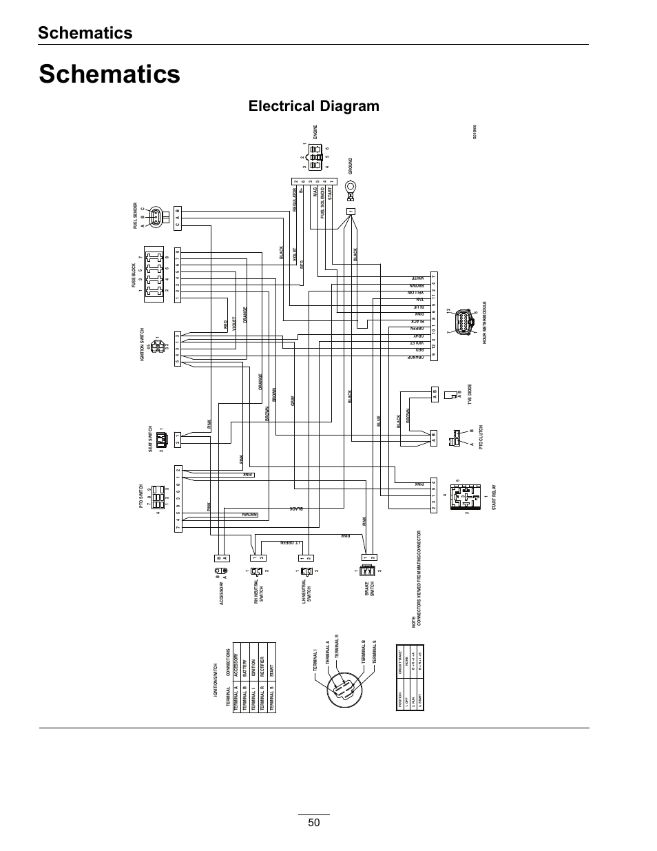
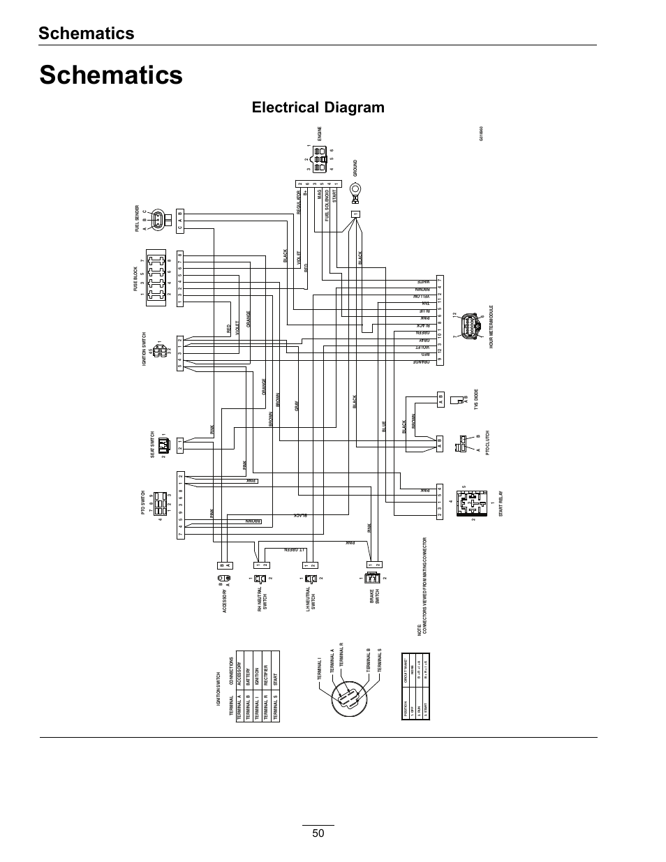
6. Electrical schematics.
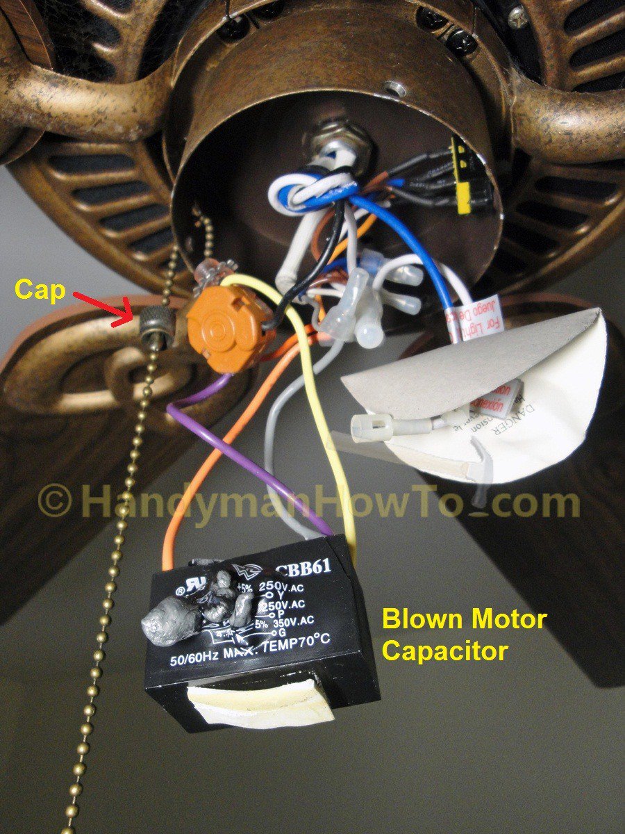
Table 5. MCU pin description versus board function. Figure 6. STM32FVGT6 block diagram. ..
NBL[], NL, NREG .. MP4.
How to Make an Ethernet Cable! – FD500R Crimp Tool Demonstration
5. DT.
LIS3. DL.

Pushbutton. LED.
SWD. USB. OSC.
F re e. I/O. Find great deals on eBay for Ceiling Fan Capacitor 5 Wire in Electrical Capacitors.
Shop with CEILING FAN CAPACITOR CBB61 uf+4uf+uf 5 WIRE V V AC. $; Buy It . 6-Padded FR Envelope RegionalBox A.
CQC certi.Find great deals on eBay for Ceiling Fan Capacitor 5 Wire in Electrical Capacitors. Shop with confidence. M12 Actuator/Sensor Distribution Boxes (Stainless Steel) ASNBL 8/LED 8-Ports (Stainless Steel Housing) Actuator/sensor distribution box with LED operation and function indicators, housing and receptacle shells in stainless steel, side-entry, 8-ports, M12 sockets, 5-poles, 1 signal per socket, with integrated control cable.
Lilly Mosh, Leo Dan, Claudia De Colombia, Elio RoCca Lucho Muñoz (Los Galos De Chile). Need service manuals for your Marine Engine and parts? Marine Power has the resources you need, including engine manuals, wiring diagrams, and more.
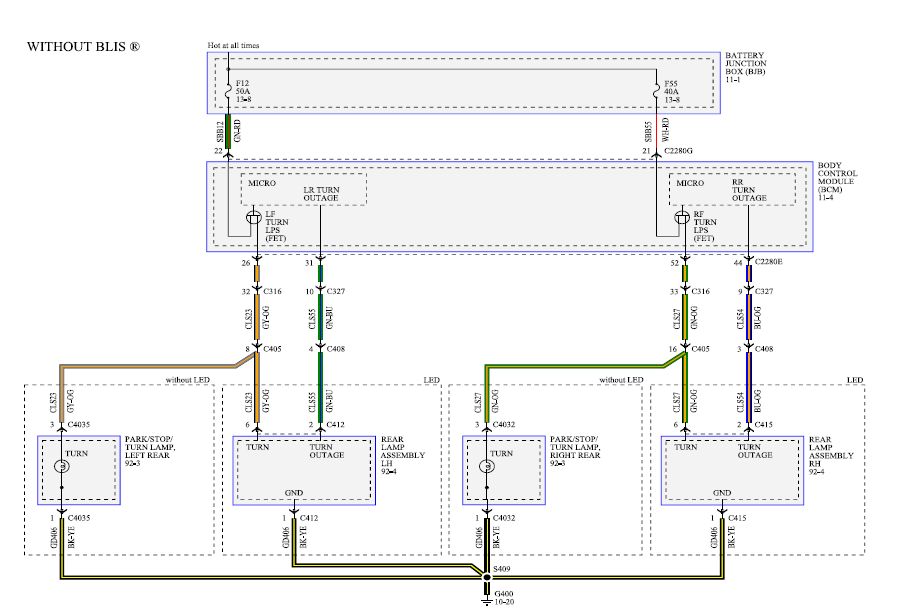
Wiring Diagram captivating product generator transfer switch img source: schematron.org Generator Automatic Transfer Switch Wiring Diagram generac automatic transfer switch owners manual installation diagrams generator or transfer switch the automatic transfer switch is used for transferring electrical wiring diagram of a generator transfer.Ceiling Fan Speed Switch RepairService and Parts Information | Marine Power USA