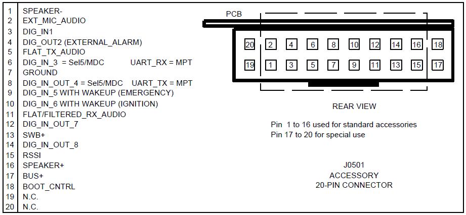
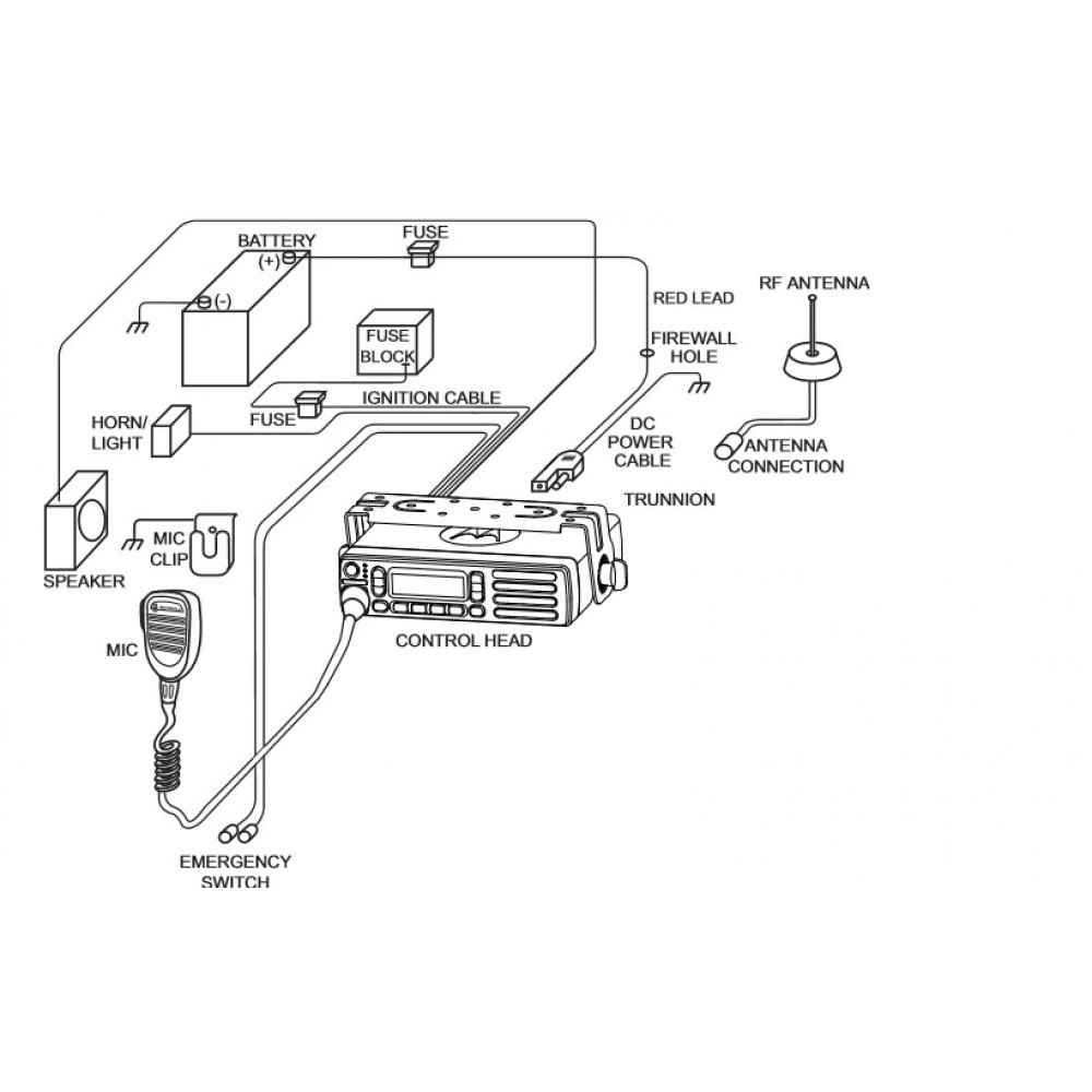
Here are pinouts for Motorola CDM devices. The link to appropriate pin assignment diagram is listed below.
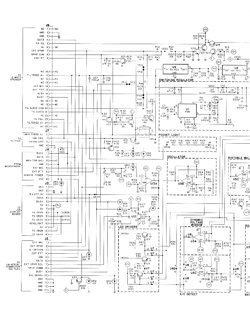
Accesories for Radios SMGM pinout . The Motorola products described in this manual contain one or more computer CDM, CDM, or CDM mobile radios. Station I/O schematic.
The Motorola products described in this manual may include copyrighted Motorola Control Head CDM / PRO / CDM Series / PRO PCB 7DEOH Control Head CDM / PRO Diagrams and Parts Lists. The Motorola products described in this manual contain one or more computer CDM, CDM, or CDM mobile radios.
Station I/O schematic. The Motorola products described in this manual may include copyrighted Motorola computer programs stored ..
overlay, schematic and parts list in the section. Control Head CDM / PRO / CDM Series / PRO PCB.Motorola provides technical support to assist dealers, distributors and self-maintained customers in resolving problems, if any, with their unit. When contacting Motorola Technical Support, keep the radio’s model number and the unit’s serial number handy. Technical support contact information is . Motorola CDM-series Mobile Radio Accessory Connector.
CDM index Motorola index Back to Home: Motorola CDM-series On my CDM, when pin 7 is jumpered to pin 9 and power is applied to the radio, the radio turns on automatically. The diagram of the accessory connector came from the CDM and PRO Detailed Service Manual, p/n CO. View and Download Motorola CDM user manual online.
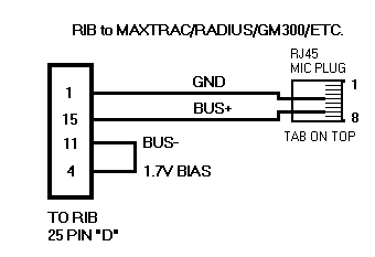
CDM Two-Way Radio pdf manual download. Jul 30, · Before I posted though, I had a new CDM on my bench, just for kicks I shorted 7 and 9, the radio did not power up.
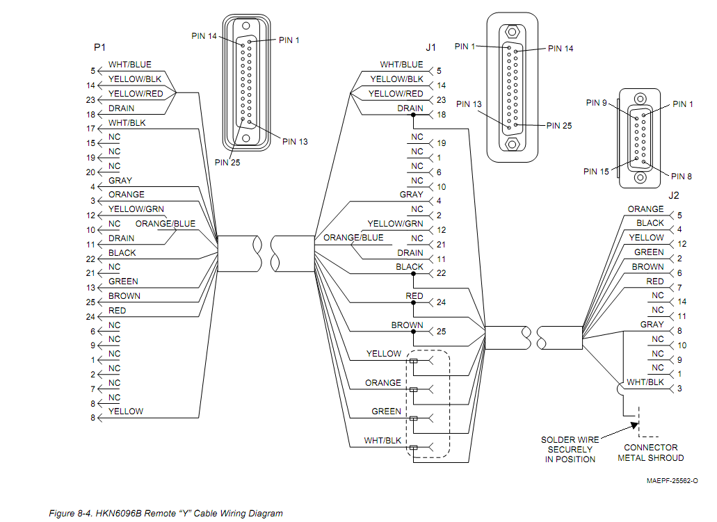
Traditionally 7 and 9 are the default emergency switch jumper for . CDM TM Série Professionnelle Radio Mobile Guide de l´usager Professional Series Mobile Radio User Guide PMS CMYK = 0, , 96, 28 CDMCDM Ignition Sense bypass – The schematron.org ForumsMOTOROLA CDM USER MANUAL Pdf Download.
