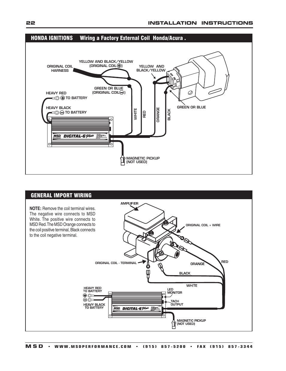
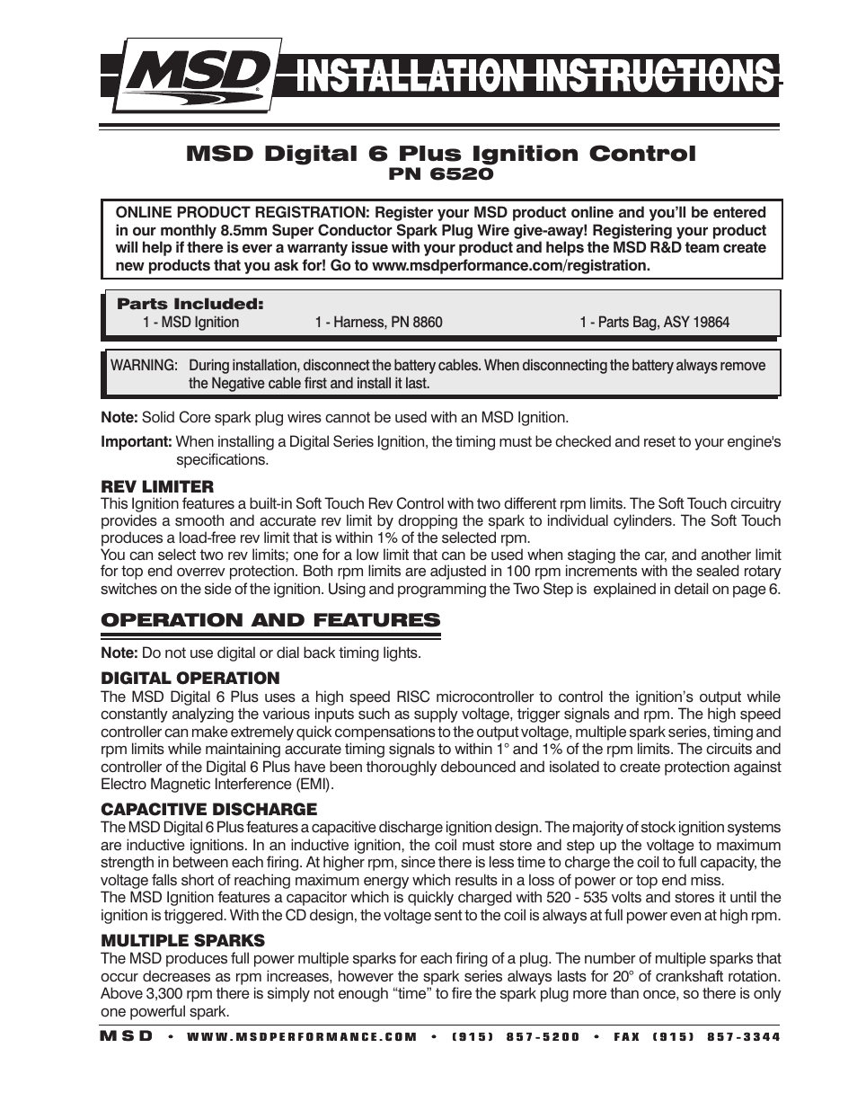
View and Download MSD installation instruction online. Digital 6 Plus Ignition Note: Solid Core spark plug wires cannot be used with an MSD Ignition . MSD Digital 6 Plus Ignition Control, PN Parts Included: 1 – MSD Note: Solid Core spark plug wires cannot be used with an MSD Ignition. ..
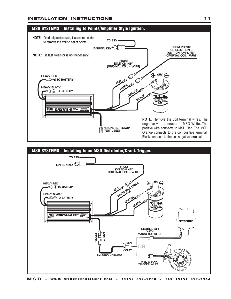
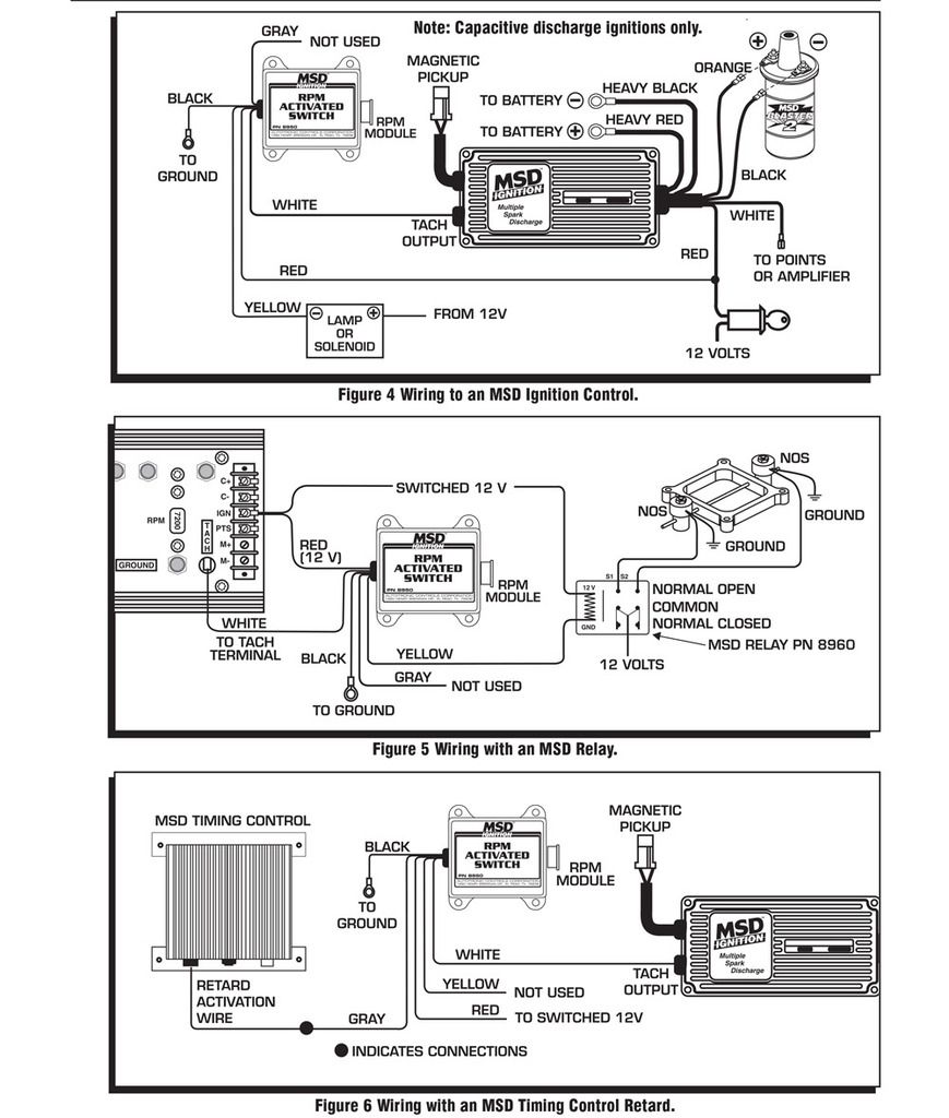
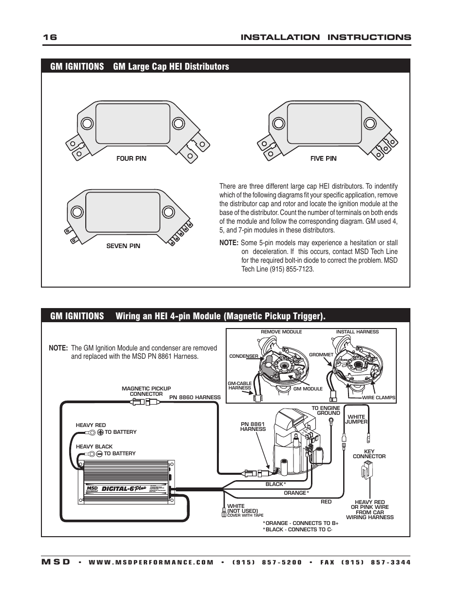
The following wiring diagrams illustrate numerous installations on different vehicles and. MSD Digital 6-Plus Ignition Control Installation User Manual.
Msd digital 6 plus Note: Solid Core spark plug wires cannot be used with an MSD Ignition. The MSD Digital-6 Plus Ignition Control combines terrific power, digital accuracy and great accessories making Instructions for Part# Spark Plug Wires.
Msd Digital 6 Plus Wiring Diagram Bestharleylinksinforhbestharleylinksinfo Or Msd Digital 6 Plus Ignition Control Pn The Msd Digital 6 Plus Ignition Can.MSD was the first company to develop and offer the multiple sparking, capacitive discharge ignition for engines. The line of MSD 6-Series Ignitions are the most popular aftermarket ignitions in the world due to our race-proven performance on the track and our reliability on the street! An MSD 6 Series Ignition Control will operate on any negative ground, 12 volt electrical system with a distributor.
The MSD can be used with 16 volt batteries and can withstand a momentary 24 volts in case of jump starts. The Ignition will deliver full voltage with a supply of 9 – 18 volts and will operate with a supply voltage as low as six volts. WIRING The MSD 5 Ignition is installed between the ignition coil and the triggering device.
It is triggered by the WHITE wire through points or an electronic ignition. It can only be used on inductive ignition systems.
Before attempting any wiring, find which diagram illustrates your vehicle’s ignition system. In .
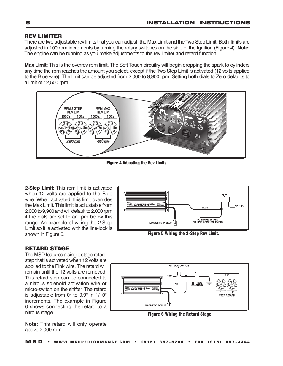
The MSD Ignition features a Tach Output Terminal on the side of the unit. This terminal provides a trigger signal for Injection Adapter to use an MSD Ignition. See pages 7 for wiring and Tach Adapter information.
Note: Vehicles originally equipped with a CD ignition control cannot use an MSD. MSD Digital 6 Plus Ignition Control, PN Parts Included: 1 – MSD Ignition 1 – Harness, PN 1 – Parts Bag, ASY WARNING: During installation, disconnect the battery cables. When disconnecting the battery always remove the Negative cable first and install it last.
Note: Solid Core spark plug wires cannot be used with an MSD Ignition.MSD Digital 6-Plus Ignition Control Installation User Manual | Page 15 / 24MSD Digital 6-Plus Ignition Control Installation User Manual | Page 2 / 24