MSD RPM Activated Switch.
PN IMPORTANT: Read the instructions before attempting the The Yellow wire is Normally Open and will activate a circuit. MSD RPM Activated Switch Installation manuals and user guides for free.
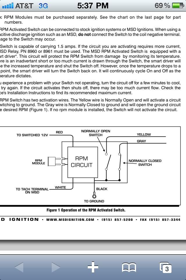
Read online or download in PDF without registration. conjunction with an RPM Activated Switch (such as MSD’s PN or PN ). WIRING.
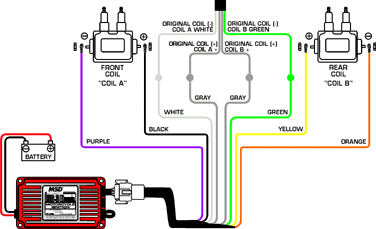
Figure 1 Connecting to a Programmable Ignition. PN Find MSD RPM Activated Switches and get Free Shipping on Orders The output wires will either supply or remove ground depending on how you wire it.
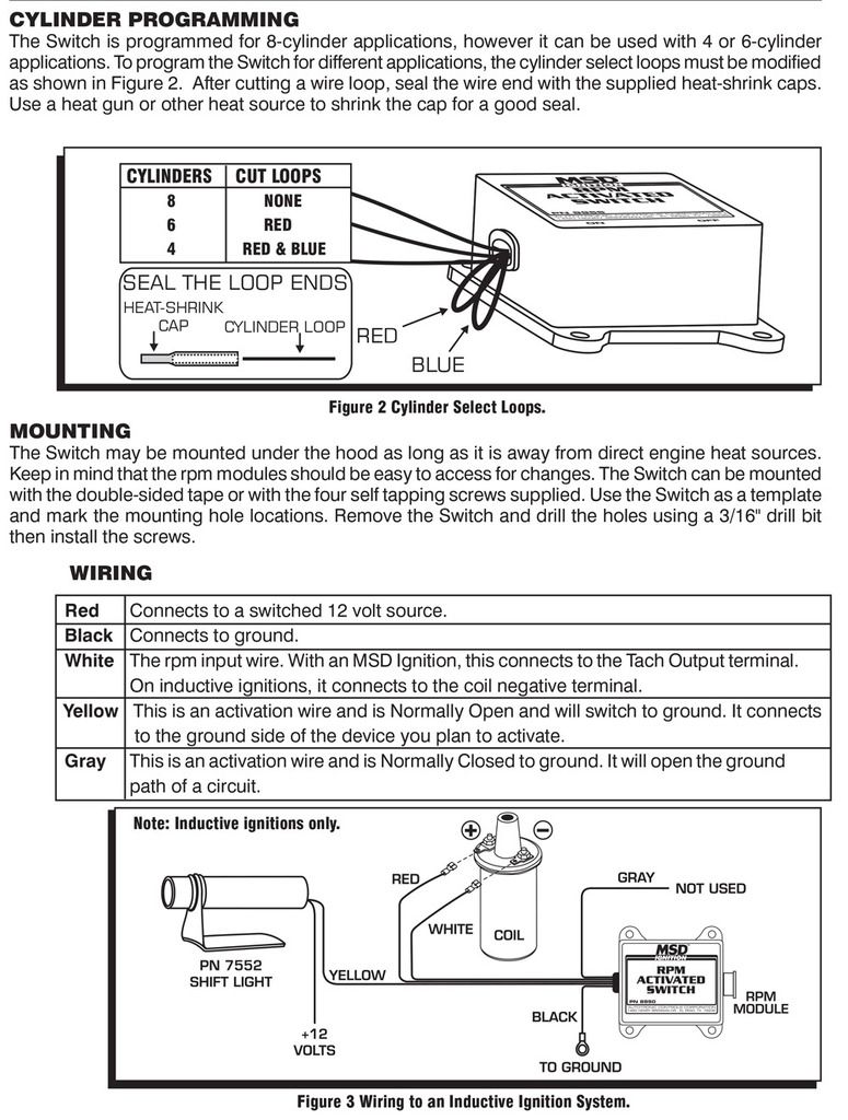
MSD RPM Activated Switch Installation manuals and user guides for free. Read online or download in PDF without registration.MSD RPM Activated Switch Figure 3 Wiring to an MSD Ignition Control. Figure 4 Wiring a PN to an inductive ignition.
PN – MSD Unit must be used on single cylinder application. PN – MSD unit must be used on 2 cylinder 4 stroke engine (waste spark).
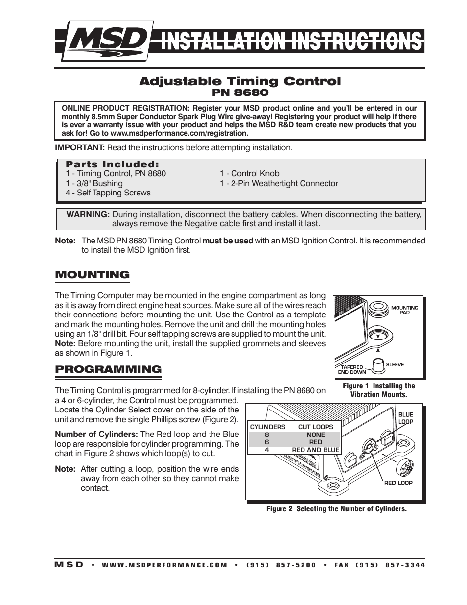
msd Using this in two drag racing vehicles for shift light and shifter solenoid. This is a must have for bracket racing to ensure RPM activation happens consistently.5/5(8). Msd Wiring Diagrams ~ thanks for visiting our site, this is images about msd wiring diagrams posted by Benson Fannie in Msd category on Nov 22, You can also find other images like wiring diagram, parts diagram, replacement parts, electrical diagram, repair manuals, engine diagram, engine scheme, wiring harness, fuse box, vacuum diagram, timing belt, timing chain, brakes diagram.
Wire Length: All of the wires of the MSD Ignition may be shortened as long as quality connectors are used or soldered in place. To lengthen the wires, use one size bigger gauge wire (10 gauge for the power leads and 16 gauge for the other wires) with the proper connections.
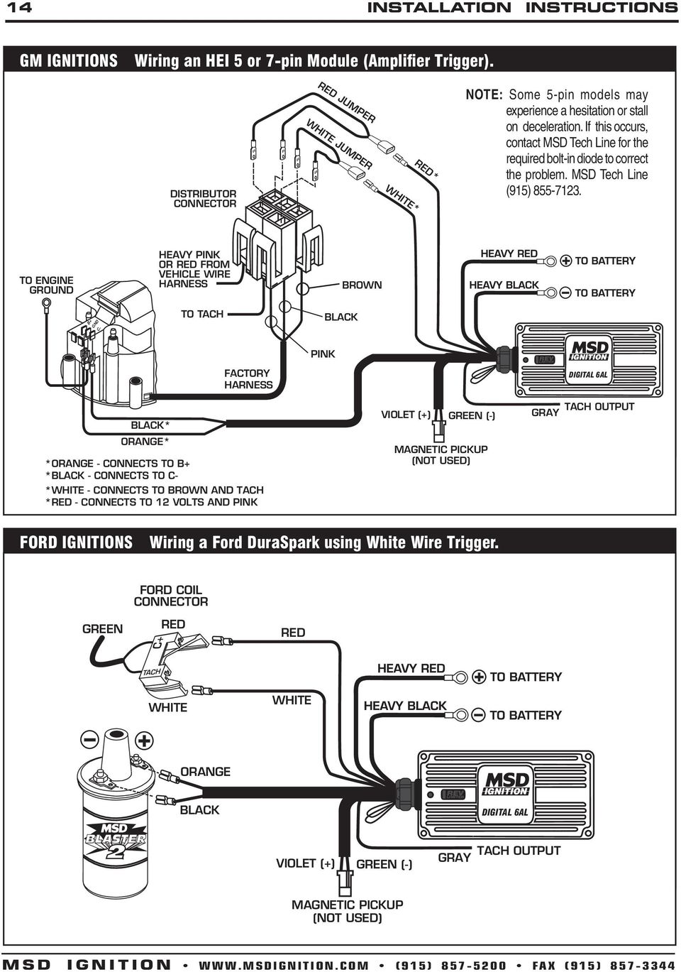
All . White The rpm input wire. With an MSD Ignition, this connects to the Tach Output terminal.
On inductive ignitions, it connects to the coil negative terminal. Yellow This is an activation wire and is Normally Open and will switch to ground. It connects MSD RPM Switch Installation Instructions.MSD RPM Activated Switch Installation User Manual | Page 3 / 4Msd Wiring Diagrams – schematron.org
